The basic terms + definitions commonly used in antenna design and RF design are provided below. Today we will review: Smith Chart, VSWR, Return Loss, and Γ or Reflection coefficient.
Smith Chart
A Smith Chart is a graphical aid designed for RF engineers to solve transmission line and matching problems. Impedance values (real and reactive) are plotted on a graph of Reflection Coefficient, Γ, using the following relationship:

Z is the input impedance of your system (for example, the impedance of the antenna you are trying to match). The value Z usually contains real and reactive components. As an example, the antenna impedance may be 30+j56. Z0 is the characteristic impedance of the measurement system such as a network analyzer. In most cases, Z0 is equal to 50 Ohms and does not have a reactive component. The antenna impedance, 30+j56, is plotted on a Smith chart and used to help determine the proper matching components and transform the load to match the 50 Ohm transmission line.
Vincident is the incident voltage, Vreflected is the reflected voltage. The ratio between these two values, and consequently Γ, will always be greater than 0, but less than one. This is because the incident voltage will always be greater than reflected due to at least some power transfer to the load antenna, no matter how poor the match. Γ, Vincident, and Vreflected are complex values.
The amount of reflected power is measured by the quantity |Γ|2 (please note that |Γ|is the magnitude of Γ). Typically, reflected power is represented in dB by the equation shown below.

For example, if ΓdB = -10 dB, then |Γ|2 = 0.1 and 10% of the incident power is reflected. In this case, 90% of the available power is transmitted into the antenna. It is typical to define the impedance bandwidth of an antenna as containing the range of frequencies in which
ΓdB £ -10 dB
Γdb is the parameter most often measured on a network analyzer. Another commonly used term is Return Loss, which is simply = -ΓdB.
Finally, this leads to an explanation of the Voltage Standing Wave Ratio (VSWR). VSWR is determined by the ratio of the peak amplitude of a standing wave to the minimum amplitude of a standing wave along the transmission line.
How to Calculate VSWR

Low values for VSWR indicate a good antenna match. For a description on how standing and traveling waves are formed, please see our blog on 'Antenna Matching Within an Enclosure Part I: Theory and Principle’.
Building off of Part I, this paper covers common antenna definitions for antenna design and RF design. Return loss, S11, antenna efficiency, and impedance bandwidth.
S11 is a measure of how much power is reflected back at the antenna port due to mismatch from the transmission line. When connected to a network analyzer, S11 measures the amount of energy returning to the analyzer – not what’s delivered to the antenna. The amount of energy that returns to the analyzer is directly affected by how well the antenna is matched to the transmission line. A small S11indicates a significant amount of energy has been delivered to the antenna. S11 values are measured in dB and are negative, ex: -10 dB. S11 is also sometimes referred to as return loss, which is simply S11 but made positive instead (Return Loss = - S11). So if the antenna Return Loss is 8 dB, S11 is -8 dB. The third and final method to measure an antenna’s ability to accept power is VSWR (voltage standing wave ratio). VSWR evaluates the ratio of the peak amplitude of the voltage of the wave on the transmission line versus the minimum amplitude of the voltage of the wave. A VSWR of 1 is ideal; this indicates that there is no reflected power at the antenna port. When the antenna and transmission line are not perfectly matched, reflections at the antenna port travel back towards the source and cause a standing wave to form. The worse the mismatch, the larger the amplitude of these reflections.
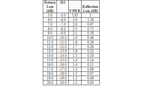
A more in-depth look into Return Loss, S11, VSWR and how they are related to the antenna impedance is provided in ‘A Concise Definition of Commonly Used Antenna Terms: Part I.’ Provided below is a chart correlating Return Loss, VSWR, and dB loss due to reflection at the antenna port.
Table 1: Return Loss, VSWR, and Reflection Loss
Radiation Efficiency is a measure of how well an antenna converts accepted power to radiated power. An efficient antenna will radiated most of the power it accepts from the transmission line. All antennas have losses associated with them, such as conductor and dielectric losses. Radiation Efficiency takes into account the loss associated in the antenna only, it should not to be confused Return Loss. The antenna accepts a certain amount of energy delivered to it by the transmission line (characterized by S11, VSWR, or return loss), and Antenna Efficiency characterizes the amount of energy lost ‘in’ the antenna after this. It is often expressed in terms of a percentage, or in dB. For example, an efficiency of 0.8 is 80%, or -0.97dB.
Radiation Efficiency (Antenna Efficiency)

Efficiency= P_radiated/P_input
*Sometimes, the term Antenna Efficiency is used instead of Radiation Efficiency.
Antenna Bandwidth
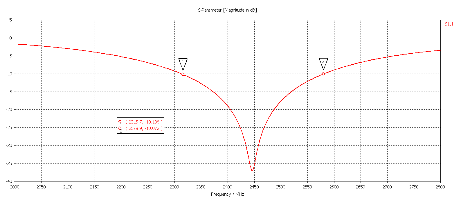
Bandwidth (sometimes just referred to as impedance bandwidth) refers to the range of frequencies a given Return Loss can be maintained. Since Return Loss is a measurement of how much power the antenna accepts from the transmission line, the impedance of the antenna must match the impedance of the transmission line for maximum power transfer. However the impedance of the antenna changes with frequency, resulting in a limited range that the antenna can be matched to the transmission line. The Bandwidth is a measure of this range. It is typically paired with a given Return Loss or VSWR value; for example the figure below has a 10 dB Return Loss Bandwidth of 260 MHz.

Figure 1: Impedance Bandwidth Measurement
Contact Antenna Design Experts Learn about our Antenna Design Services


