/filters:background_color(white)/2024-10/bl654pa-both_0.png)
BL654PA Module
Introduction
This application note describes the requirements when developing with Nordic nRF Connect SDK for the BL654PA module. It focuses on regulatory requirements and how these are met by the user application. These must be followed to ensure compliance with regulatory requirements.
Overview
Ezurio’s BL654PA modules incorporate a Skyworks SKY66112-11 front-end module. This integrates a Power Amplifier (PA) for transmitted data and a Low Noise Amplifier (LNA) for received data. The addition of this part facilitates greater operating range for the BL654PA when compared to the standard BL654 module.
When operating at the greater transmission power levels offered by the power amplifier, it is possible to exceed duty-cycle related stipulations specified by regulatory authorities. The smartBASIC core application made available to end-users implements the measures necessary to ensure all regulatory requirements are complied with. Should the end-user wish to develop a Nordic SDK-based application however, implementation of these measures will be necessary.
This application note describes the measures necessary to comply with regulatory requirements when developing with the nRF Connect SDK v3.0 or greater.
Note: At the time of writing this application note support for the BL654PA has not been implemented in Canvas SW Suite.
Assumptions
It is assumed that the developer is familiar with the nRF Connect SDK and Zephyr RTOS. This application note does not provide code examples or Zephyr configuration examples for controlling the SKY66112 FEM. The intent of this note is purely to outline the requirements that are necessary for FEM control to ensure regulatory requirements are met and certifications remain valid for the BL654PA module.
Skyworks Front-End Module Interface
The control interface to the Skyworks front-end module from the host Nordic NRF52840 is shown in the following diagram.
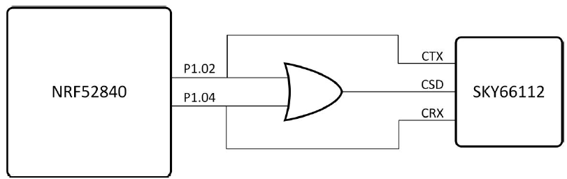
Two NRF52840 GPIO lines, P1.02 and P1.04, are used to control the front-end module. The GPIO are lines are driven to a high logic level to activate a front-end module mode. The following table describes the FEM pins interfaced with the nRF52840.
Skyworks SKY66112 control interface
| Pin | Description |
| CRX | Enables the front-end module low noise amplifier for reception |
| CSD | Places the front-end module in sleep mode, disabling both the power amplifier and low noise amplifier, when at a low logic level |
| CTX | Enables the front-end module power amplifier for transmission |
The CSD pin is connected via an OR gate to both P1.02 and P1.04 to ensure sleep mode is disabled when transmission or reception is taking place. The following table summarizes the logic associated with the control interface.
Skyworks SKY66112 control interface truth table
Mode | NRF52840 | SKY66112 | |||
| P1.02 | P1.04 | CTX | CSD | CRX | |
| Receive LNA Mode | 0 | 1 | 0 | 1 | 1 |
| Sleep Mode | 0 | 0 | 0 | 0 | 0 |
| Transmit High Power Mode | 1 | 0 | 1 | 1 | 0 |
Manual control of the NRF52840 GPIO lines that form the control interface to the SKY66112 FEM is not necessary. The SKY66112 FEM and GPIO are defined in the BL654PA Device Tree in Zephyr which will in return control the FEM and drive the GPIO lines automatically.
SKY66112 FEM Configuration
The BL654 DVK is supported in Zephyr with the BL654PA added as a variant of the BL654 DVK. The BL654PA variant (bl654_dvk/nrf52840/pa) adds the SKY66112 FEM as an additional node to the BL654 DVK DTS file which defines the pins used along with other parameters. This FEM node informs the device drivers of the FEM in which will then in return control P1.02 and P1.04 GPIO accordingly. Refer to the BL654 DVK board in Zephyr.
https://docs.zephyrproject.org/latest/boards/ezurio/bl654_dvk/doc/bl654_dvk.html
When building for the bl654_dvk/nrf52840/pa variant the bl654_dvk_nrf52840_pa.dts is added to the BL654 DVK device tree.
#include "bl654_dvk.dts"
/ { /* Information from Nordic SDK-Based Application Development and SKY66112 datasheet */ nrf_radio_fem: fem { status = "okay"; compatible = "generic-fem-two-ctrl-pins"; ctx-gpios = <&gpio1 2 GPIO_ACTIVE_HIGH>; crx-gpios = <&gpio1 4 GPIO_ACTIVE_HIGH>; ctx-settle-time-us = <23>; crx-settle-time-us = <5>; tx-gain-db = <22>; rx-gain-db = <11>; };};
&radio { fem = <&nrf_radio_fem>;};
Limitation of Transmit Power
As stated previously, when operating at the greater transmission power levels offered by the power amplifier, it is possible to exceed duty-cycle related stipulations specified by regulatory authorities. The BL654PA device tree enables the SKY66112 FEM and defines the GPIO but further software control is necessary to limit the time the transmitter is driving.
The transmit power configured by the end-user application must consider both the characteristics of the SKY66112 power amplifier and the regulatory requirements associated with the physical layer selected. These are summarized in the table below. Customer has control of nRF52840 TX RF power setting only as per this table and the resulting SKY66112 TX power is decided, i.e. the SKY66112 can be thought of as a RF gain block.
Transmit power limitations for baudrate, physical layer and SKY66112 power amplifier characteristics
NRF52840 TX Power (dBm) | SKY66112 TX Power (dBm) | PHY | ||
| 1 Mbps | 2 Mbps | Coded PHY 125 kbps | ||
| 8 | 30 | Exceeds SKY66112 output power limit | ||
| 7 | 29 | Exceeds SKY66112 output power limit | ||
| 6 | 28 | Exceeds SKY66112 output power limit | ||
| 5 | 27 | Exceeds SKY66112 output power limit | ||
| 4 | 26 | Exceeds SKY66112 output power limit | ||
| 3 | 25 | Exceeds SKY66112 output power limit | ||
| 2 | 24 | Exceeds SKY66112 output power limit | ||
| 0 | 22 | Exceeds SKY66112 output power limit | ||
| -4 | 18 | Allowed | Allowed | Not Allowed |
| -8 | 14 | Allowed | Allowed | Allowed |
| -12 | 6 | Allowed | Allowed | Allowed |
| -16 | 0 | Allowed | Allowed | Allowed |
| -20 | -6 | Allowed | Allowed | Allowed |
| -40 | -26 | Allowed | Allowed | Allowed |
Notes: For 1 Mbps and 2 Mbps BLE, the BL654PA is certified for RF TX output power of 18 dBm maximum.
For Coded PHY 125 kbps BLE, the BL654PA is certified for reduced RF TX output power of 14 dBm maximum. This ensures compliance with FCC, IC, AUS, and NZ power spectral density requirements.
Limitations of Duty-Cycle and PDU Length
Depending upon the physical layer in use, the PDU length must be restricted, and, for the 1 Mbps and 2 Mbps PHYs, the duty cycle must be restricted. These constraints are described as follows.
1Mbs and 2Mbs
For the LE 1M PHY and 2M LE PHY, the time spent by the end-user application transmitting data must be limited to comply with regulatory requirements. Over a 100ms observation period, no more than 24 milliseconds can be spent transmitting data on a single data channel. This is further dependent upon the transmit power of the radio and the widths of data packets sent.
The constraints necessary for implementation are shown in the table below.
Duty cycle limitation for 1 Mbps and 2 Mbps
NRF52840 TX Power (dBm) | SKY66112 TX Power (dBm) | PHY | Declared Maximum BLE Protocol | ||
|---|---|---|---|---|---|
| 1 Mbps | 2 Mbps | Maximum Event Length (ms) | |||
Maximum PDU Length (bytes) | |||||
| 8 | 30 | Not Allowed | Not Allowed | Not Allowed | N/A |
| 7 | 29 | Not Allowed | Not Allowed | Not Allowed | N/A |
| 6 | 28 | Not Allowed | Not Allowed | Not Allowed | N/A |
| 5 | 27 | Not Allowed | Not Allowed | Not Allowed | N/A |
| 4 | 26 | Not Allowed | Not Allowed | Not Allowed | N/A |
| 3 | 25 | Not Allowed | Not Allowed | Not Allowed | N/A |
| 2 | 24 | Not Allowed | Not Allowed | Not Allowed | N/A |
| 0 | 22 | Not Allowed | Not Allowed | Not Allowed | N/A |
| -4 | 18 | 200 | 200 | 24% (24 ms) plus margin | 11.25 |
| -8 | 14 | 251 | 251 | 24% (24 ms) plus margin | 1000 |
| -12 | 6 | 251 | 251 | 24% (24 ms) plus margin | 1000 |
| -16 | 0 | 251 | 251 | 24% (24 ms) plus margin | 1000 |
| -20 | -6 | 251 | 251 | 24% (24 ms) plus margin | 1000 |
| -40 | -26 | 251 | 251 | 24% (24 ms) plus margin | 1000 |
125kbs Coded-PHY
No duty cycle restriction is necessary when the 125 kbps Coded PHY is in use. However, the PDU length must not be allowed to exceed 251 bytes in length.
Note: 125 kbps Coded PHY transmit power is limited to 14 dBm to pass FCC TX Power spectral Density. This passes FCC Band Edge emissions, so duty cycle demonstration or declaration is not required.
Calculation of Event Length for Connection Interval
For a given Connection Interval, Event Length, and number of Connections, the maximum time available for each connection can be calculated with the following:
Maximum Event Length = Connection Interval / Connection Count
Connection Events of up to this length then occur after each Connection Interval.
A Connection Interval of 100ms for five Connections with an Event Length of 20ms is shown in the following figure.
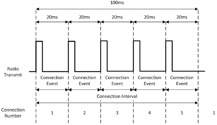
Each connection event utilizes a different randomly selected data channel.
The maximum event length usable by the end-user application must be limited to 11.25ms when at the 18dBm power level. Even with a connection interval of 11.25ms and a single connection, a different data channel is selected such that the minimum time the same channel is used is (11.25ms * 37) 416.25ms.
Channel Map
All 37 data channels must be enabled at all times to comply with regulatory requirements. Upon start-up, applications have their channel map set to enable all 37 channels by default. This must not be changed.
Note: Only central devices can request changes of the channel map. Peripheral devices must accept changes to the channel map. In this case, should less than 37 channels be enabled, the power level must be reduced to 14dBm maximum.
Verification Steps
Note: The end-user must validate their application to ensure the constraints described throughout are adhered to. A single data channel cannot be used to transmit data for more than 24 milliseconds over a 100 milliseconds observation time.
125 kbs Coded-PHY
As described in the Limitations of Duty-Cycle and PDU Length section, there is no limitation of PDU size for the 125 kbps Coded PHY, other than that from the specification. All transmitted messages must be limited to a transmit power of 14 dBm, or lower.
1 Mbs and 2 Mbs LE PHY
Duty-cycle, transmit power, and PDU length must be restricted for the 1 Mbps and 2 Mbps LE physical layers.
A spectrum analyzer (in zero span mode) should be used to verify that in all cases, with a 100-millisecond sweep time, the total duration of all packets sent does not exceed 24 milliseconds.
Note: The 24-milliseond restriction applies to each data channel. It is advised that more than one channel is observed during development to ensure the restriction is complied with across all data channels.
The worst-case duty-cycle conditions can be simulated with the following configuration.
▪ The longest packet length for the data rate being verified as defined in Table Duty cycle limitation for 1 Mbps and 2 Mbps.
▪ The worst-case connection interval that produces the maximum number of packets per connection interval.
For transmit power, all roles (advertising, scanning/initiating, etc.) should be verified to ensure the limits defined in Table Transmit power limitations for baudrate, physical layer and SKY66112 power amplifier characteristics are never exceeded.