/filters:background_color(white)/2024-03/Lyra%2024%20-%20Collection1.png)
Introduction
The Lyra 24 series modules have two power modes (in AT firmware):
- Run mode – Factory default mode is the Lyra 24 series the low power UART is disabled which allows AT commands to be sent over UART. At power up, the AT firmware does BLE advertising and waiting for BLE connection to be made and to receive AT commands over the UART.
- Sleep mode (Low Power UART Mode) – The module is placed in Sleep mode (also called Low power UART mode in AT firmware user guide document). The module wake up from sleep if any BLE event is triggered.
This guide demonstrates the current consumption of sleep mode using the AT firmware by putting the module into constant sleep (BLE radio advertising turned off and low power UART enabled, etc.).
Requirements
- Current measuring digital multimeter (DMM) that can measure down to 0.4uA. For this document, the Fluke 289 is used. The Fluke85 is also suitable.
- Use the appropriate Lyra 24 series development board and AT firmware specific for the particular Lyra 24 series module.
Table 1: Development Board, AT Firmware and Bootloader part numbers
| Development Kit Part Number and Description | AT Firmware Part Number and Description | Bootloader |
|---|---|---|
| 453-00148-K1 - Lyra 24P Series - Development Kit - Bluetooth PCB Module (20dBm) with RF Trace Pad | 480-00289-R133.5.1.16 | 480-00288-R133.4.0.6 |
| 453-00145-K1 - Lyra 24P Series - Development Kit - Bluetooth PCB Module (20dBm) with integrated antenna | 480-00259-R131.5.1.17 | 480-00262-R131.4.0.4 |
| 453-00142-K1 - Lyra 24P Series - Development Kit - Bluetooth PCB Module (10dBm) with integrated antenna | 480-00224-R129.5.1.43 | 480-00230-R129.4.0.10 |
| 453-00170-K1 - Development Kit, SIP, LYRA 24S, Integrated Antenna | 480-00270-R130.5.1.16 | 480-00231-R130.4.0.2 |
- Lyra 24 series AT firmware for the particular module variant can be found at: https://github.com/LairdCP/Lyra_24_Firmware
- Windows PC and Micro USB to USB (Type-A) Cable – provided with development kit.
- UwTerminalX by Laird Connectivity available at https://github.com/LairdCP/UwTerminalX/release
- For programming instructions, see Appendix: Loading the AT Firmware into Lyra 24 Series Module on Lyra 24 Series Development Board
Development Kit Setup
To set up the Lyra 24 series development board, complete the following steps:
- Modification 1: Cut solder bridge SB3 (on bottom side of board) and solder 2-pin header into J5, as shown in Figure 1.
- Modification 2: Bend pin 9 of header J1 by 90 degrees for ease of access (silkscreen PB3, which is SIO5 in AT firmware), and connect fly lead as shown in Figure 1.
- Modification 3: Bend pin 3 of header J1 by 90 degrees for ease of access (ground pin).
To measure the module’s current consumption, connect the current measuring DMM to J5 on the board (Figure 1).
Note: After the test is complete, remember to replace the jumper on J5. - Connect the Lyra 24 series development board to PC via USB cable.
For more information on the Lyra 24 series development kit, see the Lyra 24P series or Lyra 24S DVK User Guide at:
https://www.ezurio.com/lyra24-series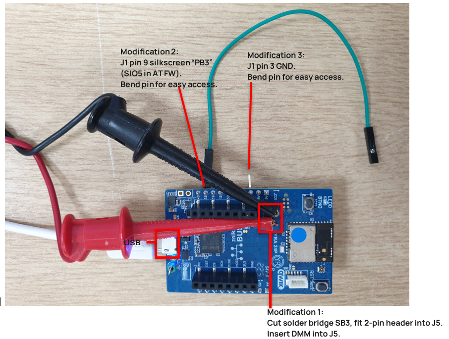
Figure 1: Lyra 24 series development board modifications for adding J5 pin header (cut SB3), bend J1 pin 9 (PB3), J1 pin 3 (GND)
Entering AT Firmware Low Power Sleep Mode over the UART
- Connect the Lyra 24 series development board USB connector to your PC via the included USB-A to USB micro cable.
- Ensure that the current measuring DMM is connected to J5 before the development kit is powered up (or else the board will not be powered).
- Ensure that the Windows Device Manager displays a new virtual COM port for the USB to Serial adapter.
Open UwTerminal with the settings shown in Figure 2.
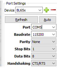
Figure 2: COM port settings
Press Return. Response should be OK.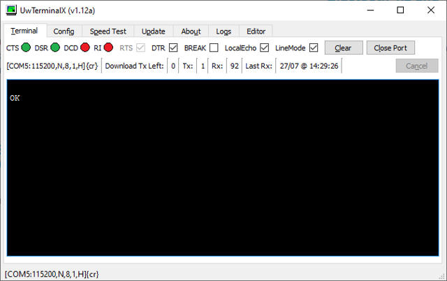
Figure 3: Press return key, response ok
- To Reset the module to factory defaults, send the command AT&F and press Return. Response should be OK. See Figure 4.
- Set the pin to be used for low power mode. in this example we use PB3 (SIO5). Any can be used. Change the SIO number by sending the command ATS109=5 and press Return. Response is OK. See Figure 4.
- Ensure the UART time out value is at least 250ms by sending the command ATS213=250 and pressing Return. Response is OK. See Figure 4.
Save this to the non volatile memory by sending the command AT&W and then press return key. Response is OK. See Figure 4.
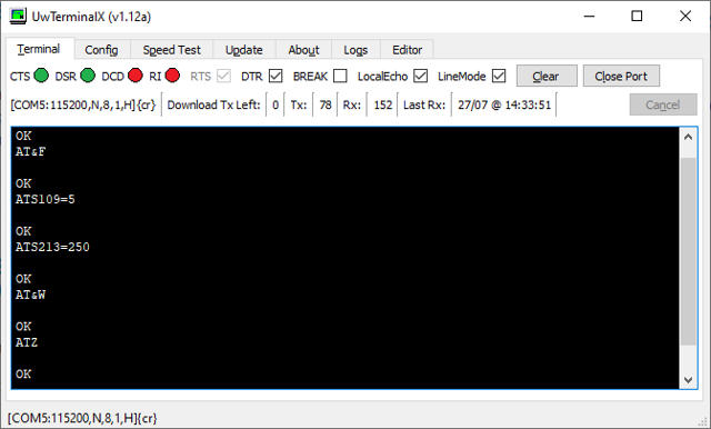
Figure 4: AT commands sent and responses
Reset the device by sending the command ATZ and pressing Return. Response is OK. See Figure 4.- Low power mode is now active. To send commands, ensure pin 19 of J1 (silkscreen “PB3”) is pulled high and press Return to verify that the module responds with OK. See Figure 5. When returning to low power mode the pin can be pulled lowed externally or left floating since the pin is internally pulled low.
While keeping pin 9 of J1 (silkscreen “PB3”) pulled high, send the command AT+LADVX and press Return. This stops any BLE advertisements, making it easier to measure sleep current with the BLE radio inactive. Response is OK. See Figure 6.
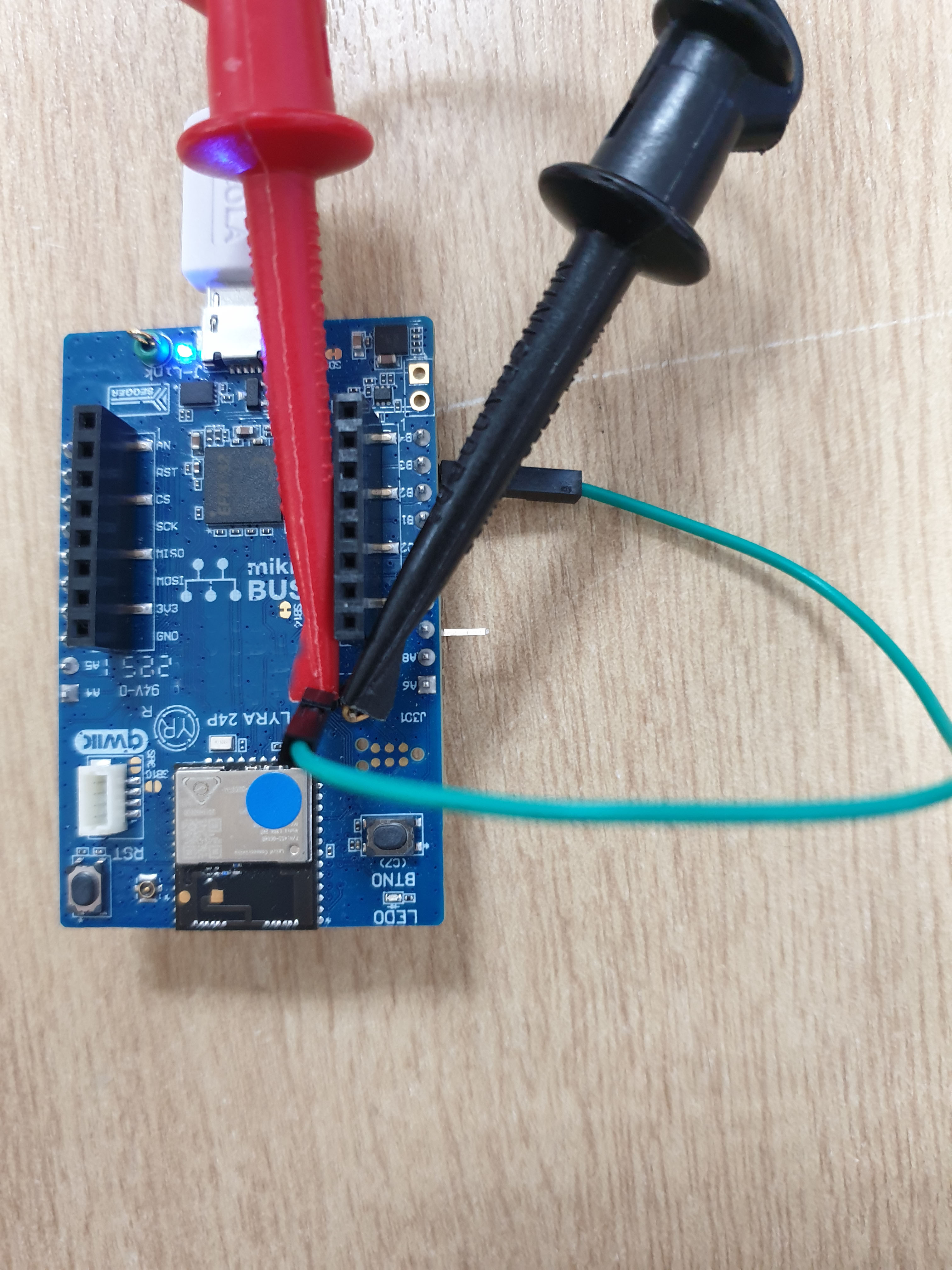
Figure 5: Pin 9 of J1 (PB3, SIO5) pulled high to VDD by taking green colored fly lead to pin 2 of J5
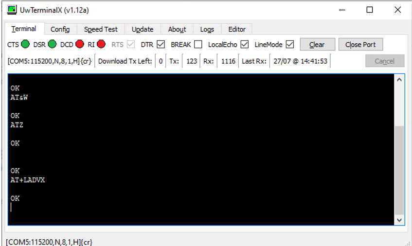
Figure 6: AT+LADVX command sent while PB3 (SIO5) held high, and terminal responses
Pull low to ground pin 9 of J1 (silkscreen PB3, SIO5 in AT firmware) by taking green colored fly lead to pin 3 of J1 (GND). This causes the module to enter low power sleep mode. See Figure 7. Now you may measure the sleep current.

Figure 7: Pin 9 of J1 (PB3, SIO5) pulled LOW to GND by taking green colored fly lead to pin 3 of J1 GND
Power cycle and repeat steps to measure sleep current.
Measured Sleep mode current consumption - 453-00148-K1 - Lyra 24P Series - Development Kit - Bluetooth PCB Module (20dBm) with RF Trace Pad
The measured sleep current is 3.16uA in Figure 8. The sleep current target is about 3.36uA, which is typical at 25°C temperature.
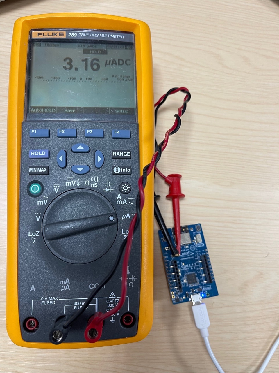
Figure 8: Lyra 24P Bluetooth PCB Module (20dBm) with RF trace pad module Sleep current at 25°C temperature with AT firmware
Note: Once you’re done with the current measurement, place the jumper back on J5. Otherwise, the Lyra 24 series module is not powered through the USB port; it is powered parasitically instead.
Note: In low power sleep mode the P module’s MCU is in EM2 mode, 256kB RFAM and full RAM retention (2.9uA) + RTC running from LFRCO in precision mode (0.459uA), the typical current consumption expected is therefore 3.36uA typical.
Measured Sleep mode current consumption - 453-00145-K1 - Lyra 24P Series - Development Kit - Bluetooth PCB Module (20dBm) with Integrated Antenna
The measured sleep current is 3.21uA in Figure 9. The sleep current target is about 3.36uA, which is typical at 25°C temperature.
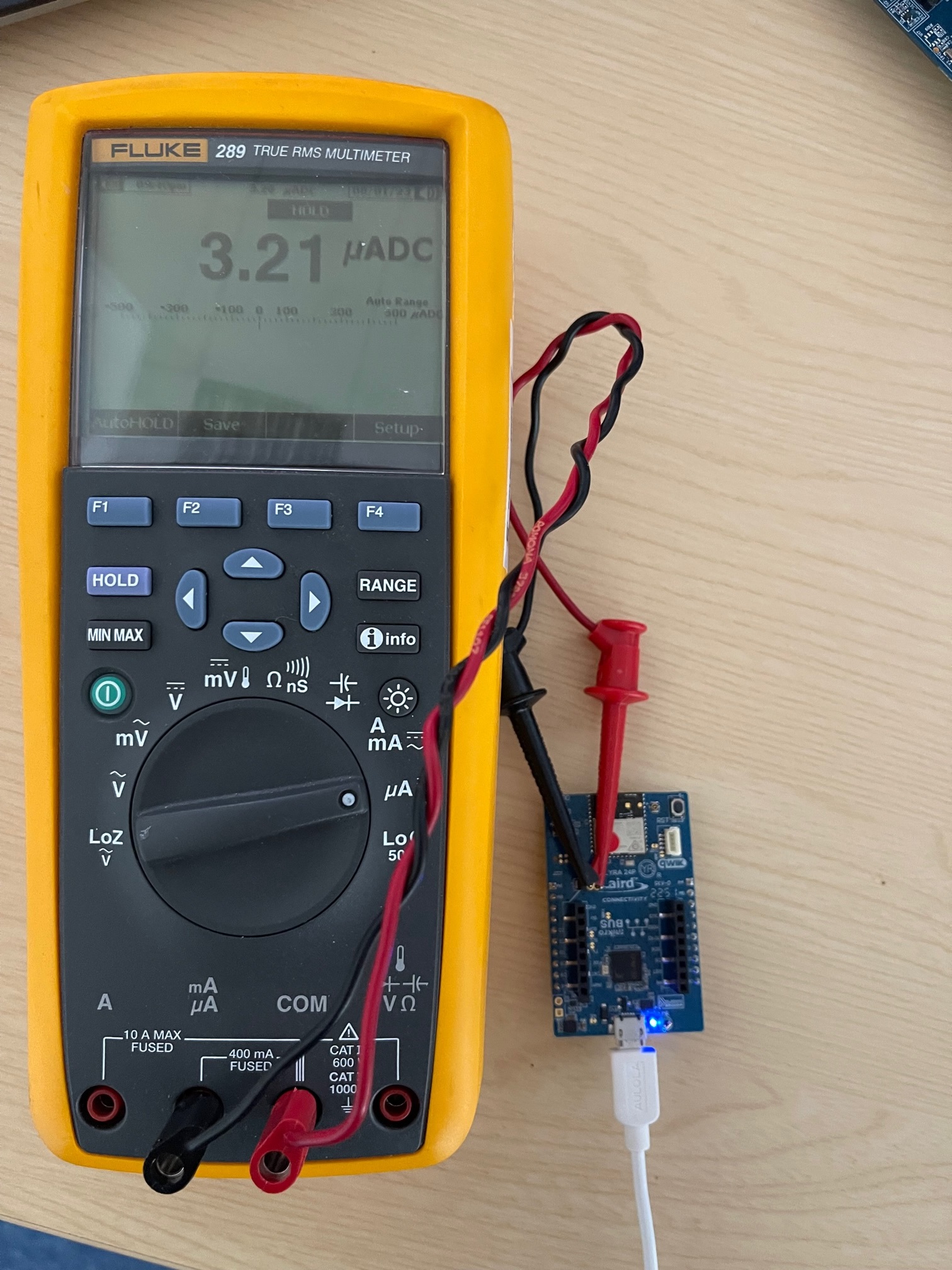
Figure 9: Lyra 24P Bluetooth PCB Module (20dBm) with Integrated Antenna module Sleep current at 25°C temperature with AT firmware
Note: Once you’re done with the current measurement, place the jumper back on J5. Otherwise, the Lyra 24 series module is not powered through the USB port; it is powered parasitically instead.
Note: In low power sleep mode the Lyra 24P series module’s MCU is in EM2 mode, 256kB RFAM and full RAM retention (2.9uA) + RTC running from LFRCO in precision mode (0.459uA), the typical current consumption expected is 3.36uA typical.
Measured Sleep mode current consumption - 453-00142-K1 - Lyra 24P Series - Development Kit - Bluetooth PCB Module (10dBm) with Integrated Antenna
The measured sleep current is 3.21uA in Figure 10. The sleep current target is about 3.36uA, which is typical at 25°C temperature.
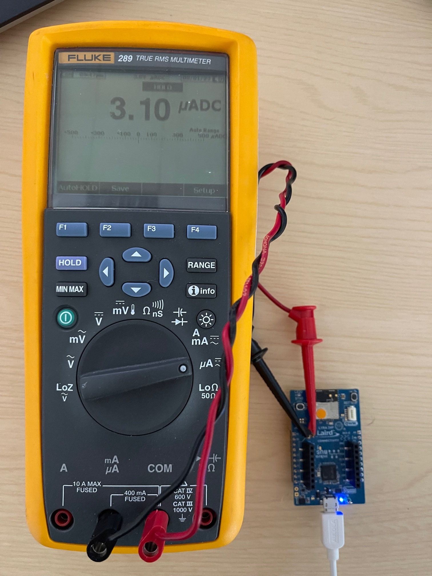
Figure 10: Lyra 24P Bluetooth PCB Module (10dBm) with Integrated Antenna module Sleep current at 25°C temperature with AT firmware
Note: Once you’re done with the current measurement, place the jumper back on J5. Otherwise, the Lyra 24 series module is not powered through the USB port; it is powered parasitically instead.
Note: In low power sleep mode the Lyra 24P series module’s MCU is in EM2 mode, 256kB RFAM and full RAM retention (2.9uA) + RTC running from LFRCO in precision mode (0.459uA), the typical current consumption expected is 3.36uA.
Measured Sleep mode current consumption - 453-00170-K1 - Development Kit, SIP, LYRA 24S, Integrated Antenna
The measured sleep current is 3.16uA in Figure 11. The sleep current target is about 3.56uA, which is typical at 25°C temperature.
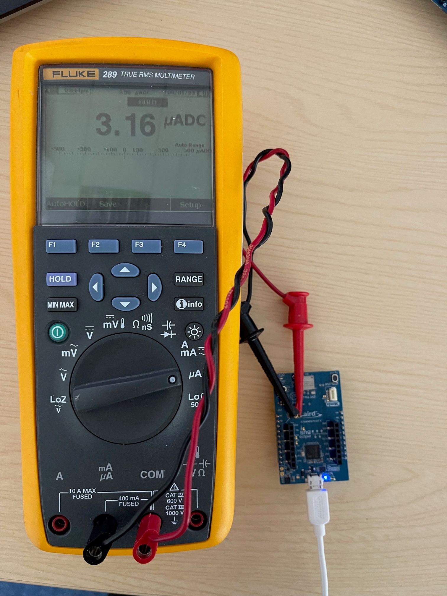
Figure 11: Lyra 24S Bluetooth PCB Module (10dBm) with Integrated Antenna module Sleep current at 25°C temperature with AT firmware
Note: In low power sleep mode the Lyra 24S module’s MCU is in EM2 mode, 256kB RFAM and full RAM retention (3.1uA) + RTC running from LFRCO in precision mode (0.459uA), the typical current consumption expected is 3.56uA. The result shown in Figure 11 is slightly lower than the expected value.
Appendix: Loading the AT Firmware into Lyra 24 Series Module on Lyra 24 Series Development Board
To load the AT firmware onto the Lyra 24 series modules (on the Lyra 24 series development board, follow these steps:
- Download the Lyra 24 series AT firmware for the particular module variant can be found at https://github.com/LairdCP/Lyra_24_Firmware
Save in a local folder, such as C:\temp1 - To load Lyra 24 series AT firmware, Silabs Simplicity Studio (and Flash programmer inside) is main method, but here we show an alternative method using tool called SEGGER J-Link V7.88n (downloadable from https://www.segger.com/downloads/jlink/ or use latest currently V7.88n) and inside that J-Link Commander V7.88n.
- In this example, we connect the 453-00148-K1development boardto the PC via USB.
On Windows, click the Start menu, then SEGGER J-Link V7.88n, and then J-Link Commander V7.88n.
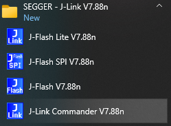
J-Link Commander launches as shown in Figure 12.
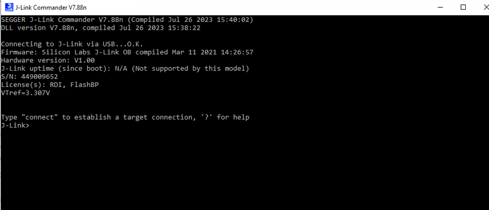
Figure 12: Starting J-Link Commander V7.88n
Type connect and press return. The terminal returns a response as shown below:
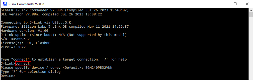
Figure 13: Send connect and response
- Type ? and press return. In response, a dialog appears and in the dialog box “Device” cell type BGM240PB.
When the three filtered options appear, select device BGM240PB32VNN (for the 453-00148-K1 - Lyra 24P DVK – Bluetooth PCB Module (20dBm) RF Trace Pad) as shown in Figure 14.
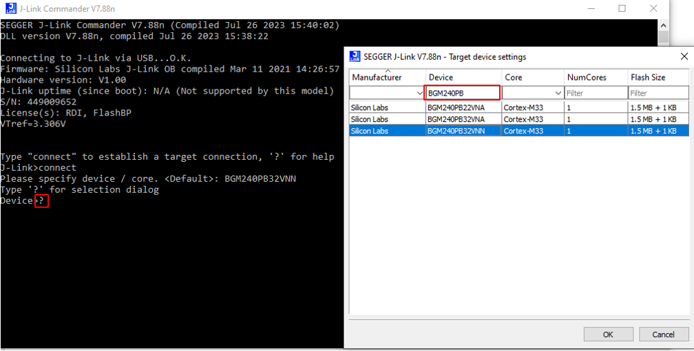
Figure 14: Sending help command ? and response a dialog box to select appropriate device
Note: The following are the four device options for Lyra 24 Series development boards:BGM240PB32VNN: 453-00148-L1 – Lyra 24P DVK – Bluetooth PCB Module (20dBm), RF Trace Pad
BGM240PB32VNA: 453-00145-K1 - Lyra 24P DVK - Bluetooth PCB Module (20dBm), Integrated antenna
BGM240PB22VNA: 453-00142-K1 - Lyra 24P DVK - Bluetooth PCB Module (10dBm), Integrated antenna
BGM240SB22VNA: 453-00170-K1 - Lyra 24S DVK, Integrated Antenna
Click OK. The terminal returns the response shown in Figure 15.
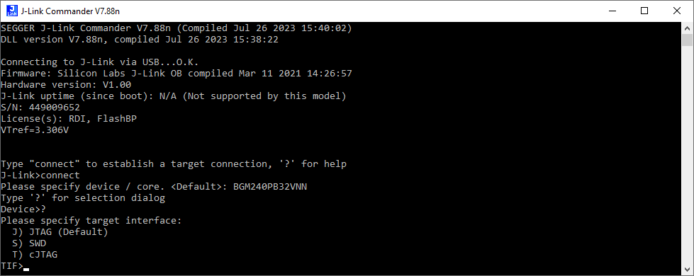
Figure 15: Terminal response
Type SWD and press Return. Figure 16shows response (default 4000 kHz).
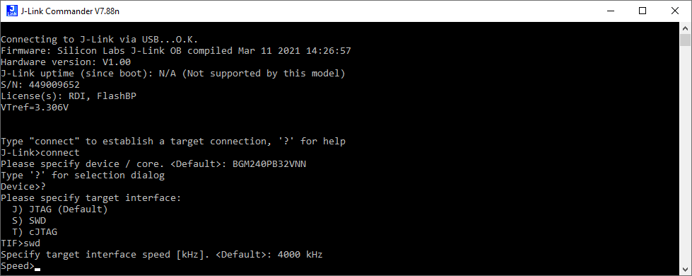
Figure 16: SWD command response
Press Return. The response is as shown inFigure 17.

Figure 17: Response to pressing return key
We assume the Lyra 24 series module has the bootloader firmware installed (default). To load AT firmware (in this example, for the Lyra 24P Bluetooth PCB Module (20dBm) with RF Trace Pad module variant), type the following command:
loadfile c:\temp1\480-00289-R133.5.1.16.hex
Press Return. The response is as shown in Figure 18.
Note: In this example, c:\temp1 is the location where the AT firmware is located. The AT firmware is per Lyra 24 series module part number, so make sure to load the correct AT firmware for the module part number. See Table 1 for details.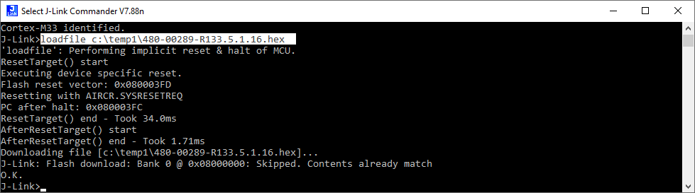
- Power cycle the development board. Close J-Link Commander V7.88n.
Further Information
Additional documents are also accessible from the Documentation tab in the Lyra 24 Series Bluetooth Product Page.
| Version | Date | Notes | Contributor(s) | Approver |
|---|---|---|---|---|
| 1.0 | 1 Aug 2023 | Initial Release | Raj Khatri | Jonathan Kaye |
| 1.1 | 2 Aug 2023 | Updated measurements and notes added | Leo Genuardi | Jonathan Kaye |
| 2.0 | 11 Mar 2025 | Ezurio rebranding | Sue White | Dave Drogowski |
| 3.0 | 1 Dec 2025 | Converted to Confluence | Dave Drogowski | Dave Drogowski |
Ezurio’s products are subject to standard Terms & Conditions.