/filters:background_color(white)/2024-12/flexpifa-flexpifa6e_0-1.png)
Features and Benefits
|
|
| SPECIFICATIONS | |
|---|---|
| Frequency (MHz) | 2400 - 2480 |
| Peak Gain (dBi) | +2.0 |
| Average Gain (dBi) | > -1.5 |
| VSWR (MHz) | < 2.0:1 |
| Impedance (Ω) | 50 |
| Polarization | Linear |
| MECHANICAL SPECIFICATIONS | ||
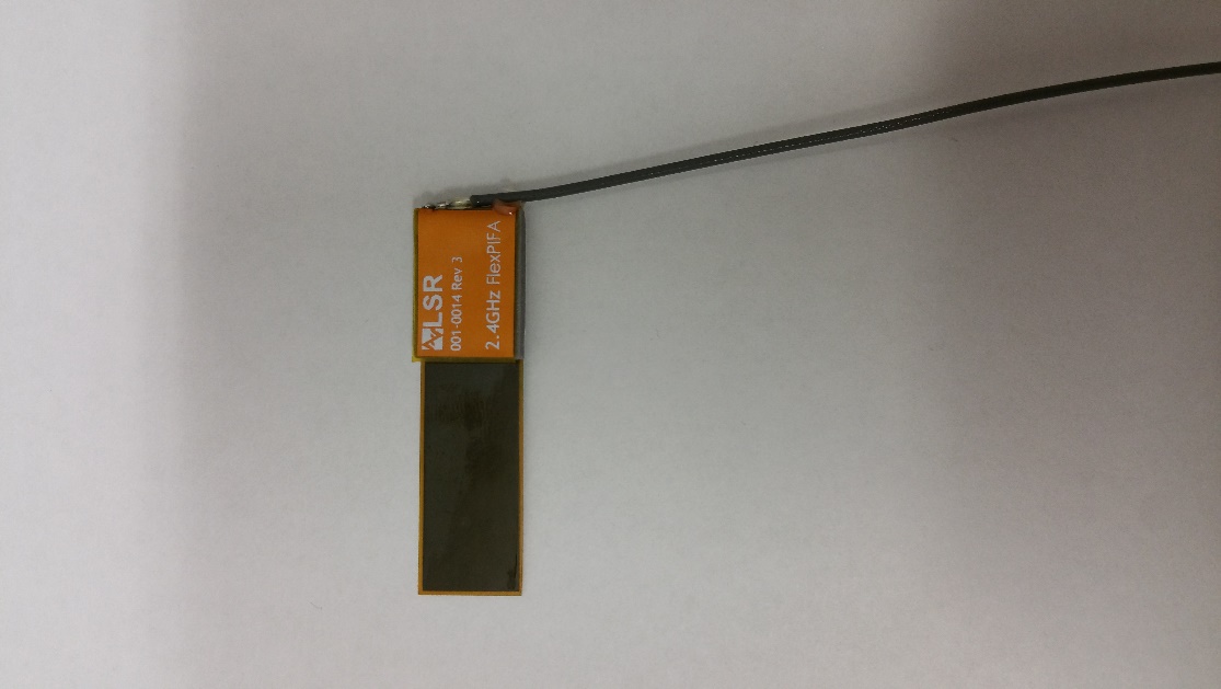
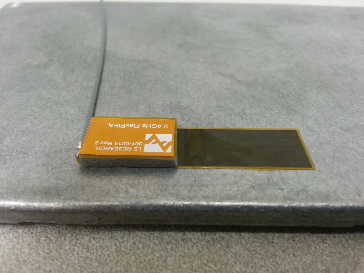
| Antenna Type | Flexible Planar Inverted F Antenna (FlexPIFA) | |
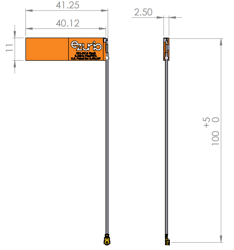
| Dimensions – mm (inches) | 40.1 x 11.0 x 2.5 (1.58 x 0.43 x 0.098) | |
| Weight – g (oz.) | 1.13 (0.040) | |
| Color | Clear yellow | |
| Adhesive | 3M 100MP | |
| Connector Mating Height (max) – mm | MHF1 (U.FL) | 2.5 |
| MHF4L | 1.4 | |
| ENVIRONMENTAL SPECIFICATIONS | ||
| Operating Temperature – °C (°F) | -40 to +85°C (-40 to +185°F) | |
| Material Substance Compliance | RoHS | |
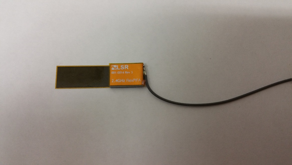
Configuration
| PART NUMBER | CABLE LENGTH | CONNECTOR |
| 001-0014 | 100 mm | MHF1 |
| 001-0022 | 100 mm | MHF4L |
| 001-0025 | 100 mm | MHF1 |
| EFB2400A3S-13MHF1 | 130 mm | MHF1 |
| EFB2400A3S-22MHF1 | 220 mm | MHF1 |
Note: Specifications are based on the 100mm cable length, standard antenna version with MHF1 / U.FL connector. Varying the cable length or type or connector will cause variations in these antenna specifications.
Mechanical Configuration
Physical Dimensions of 001-0014, 001-0022 and EFB2400A3S-22MHF1 (Right hand orientation)
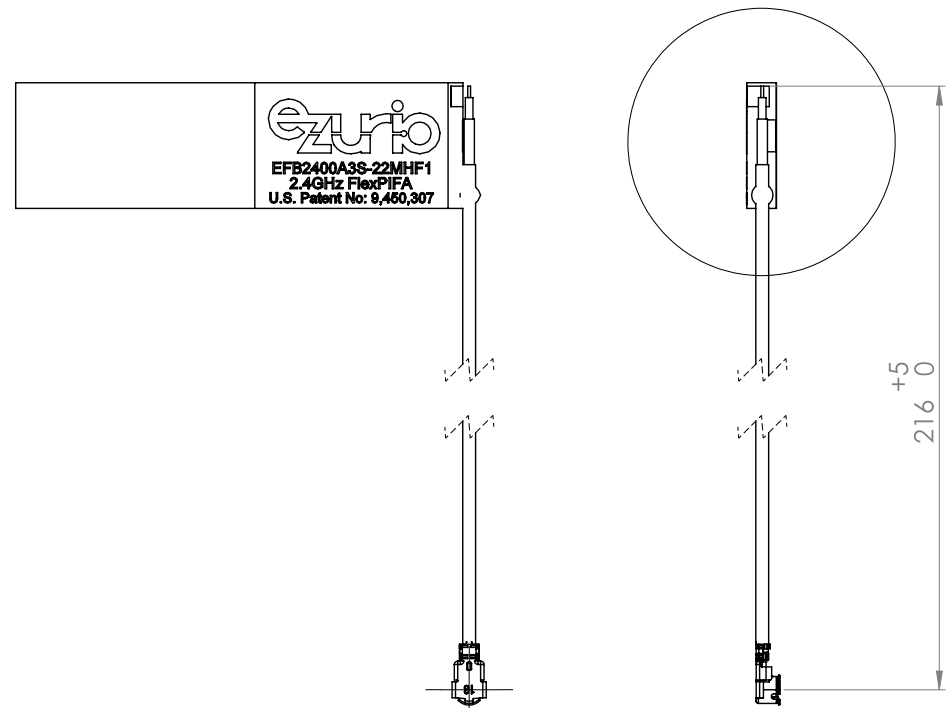
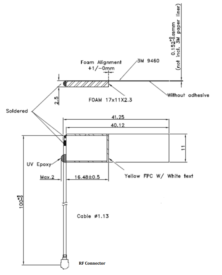
Physical Dimensions of EFB2400A3S-13MHF1
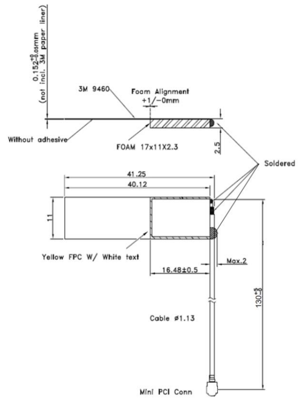
Physical Dimensions of 001-0025 (Left hand orientation)
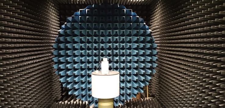
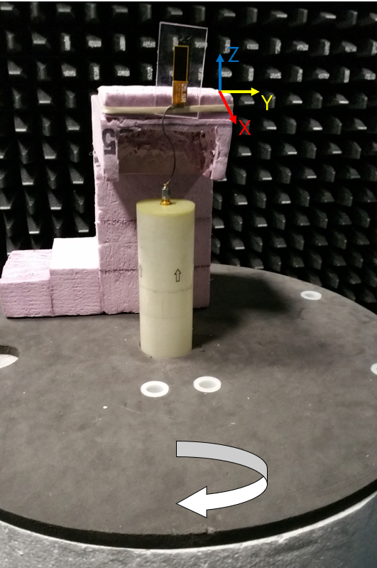
Test Setup
Antenna measurements such as VSWR were measured with an Agilent E5071C vector network analyzer. Radiation patterns were measured with a CMT Planar 804/1 vector network analyzer in a Howland Company 3100 chamber equivalent. Phase center is nine inches above the Phi positioner.
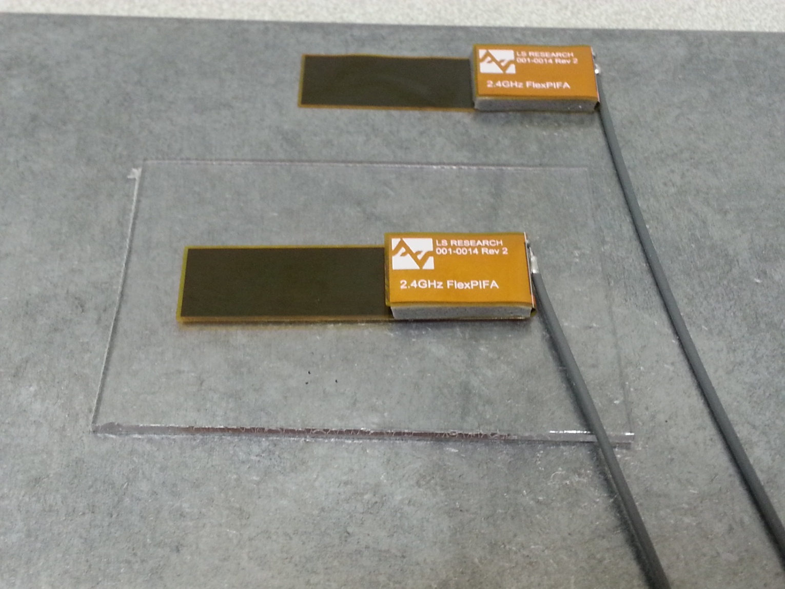
Flat surface measurements were done with the antenna centered on a 1.5 mm-thick plate of polycarbonate. Curved surface measurements were taken by placing the antenna on the inside and outside of different diameter PVC tubing.
Flat Surface Antenna measurements
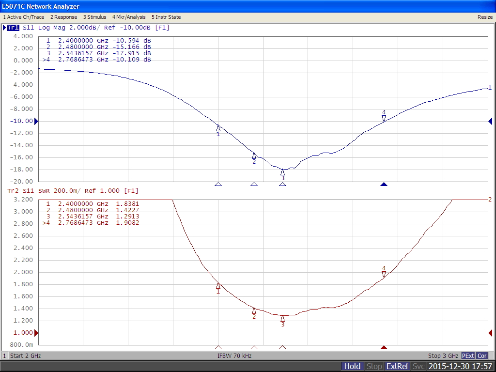
VSWR
Flat surface Antenna Radiation Performance
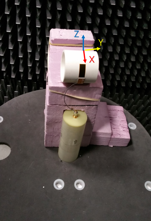
FlexPIFA centered on a 1.5 mm-thick plate of polycarbonate
Antenna Measurement Set-Up
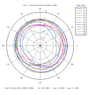
Azimuthal Conical Cuts at 2400 MHz
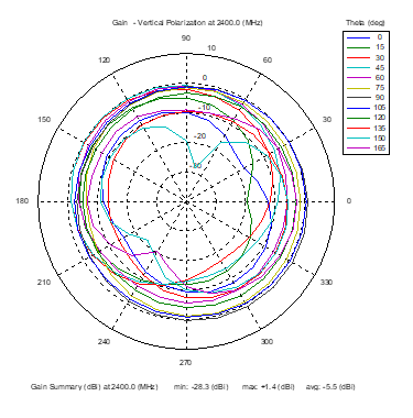 | 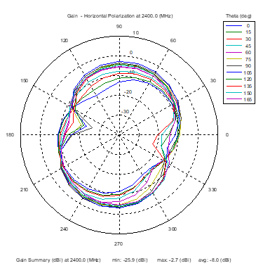 | 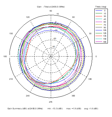 |
| Vertical, horizontal, and total gain patterns – 2400 MHz | ||
3D Plots at 2400 MHz
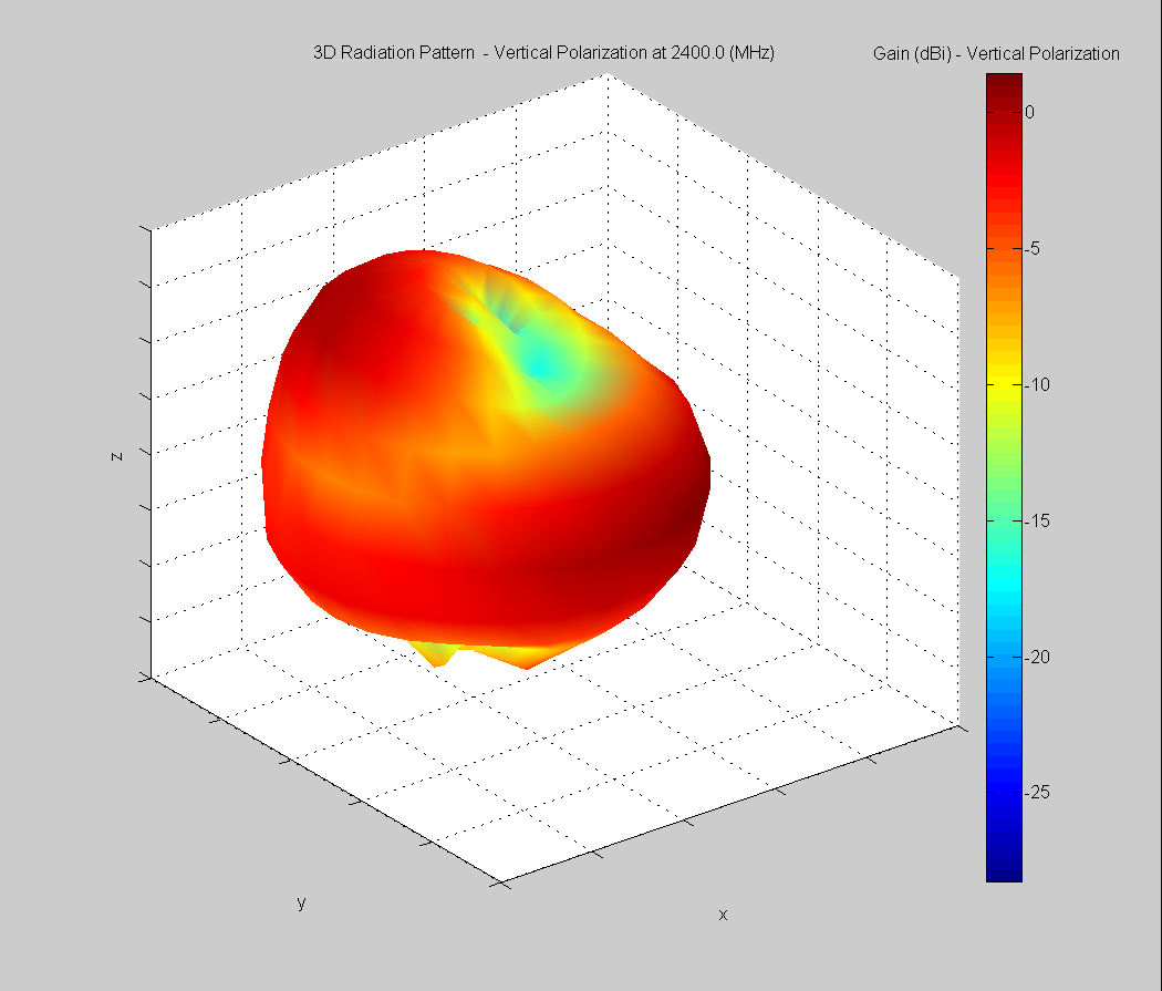 | 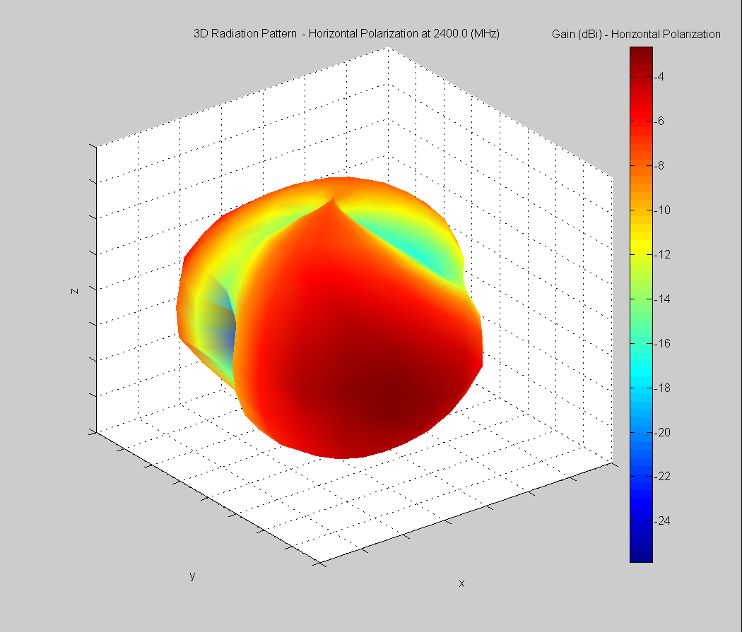 | 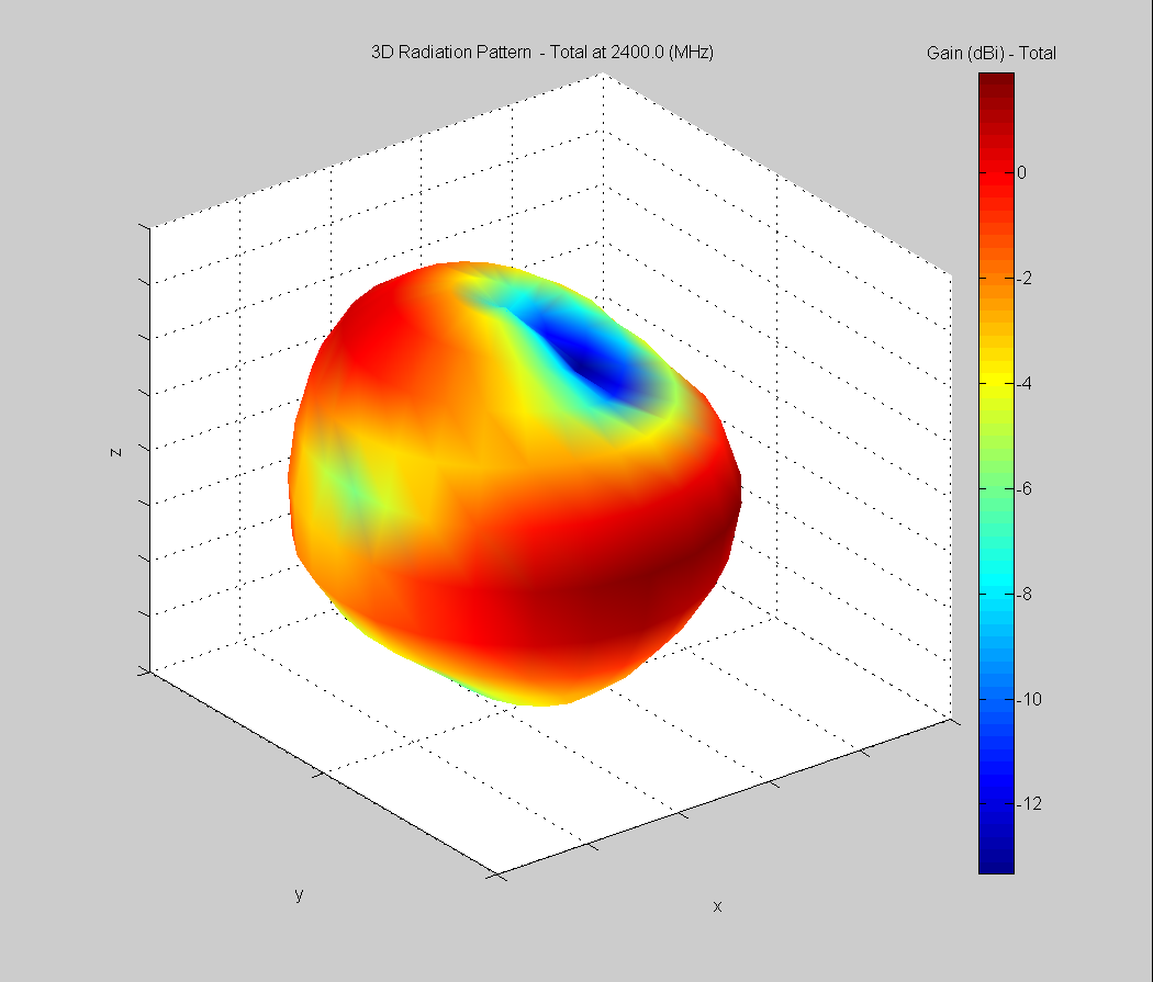 |
| Vertical, horizontal, and total gain plots – 2400 MHz | ||
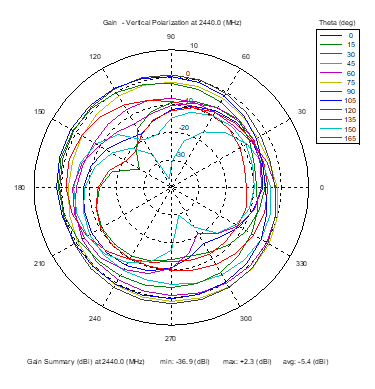
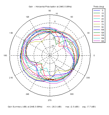
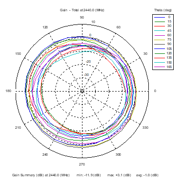
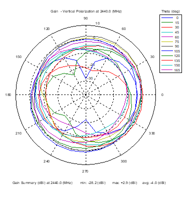
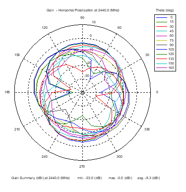
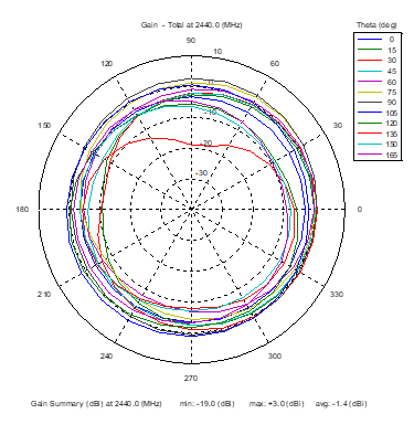
Azimuthal Conical Cuts at 2440 MHz
 | 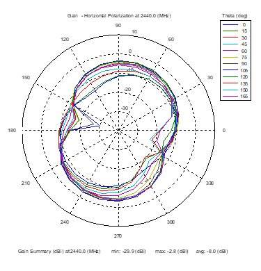 | 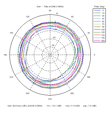 |
| Vertical, horizontal, and total gain patterns – 2440 MHz | ||
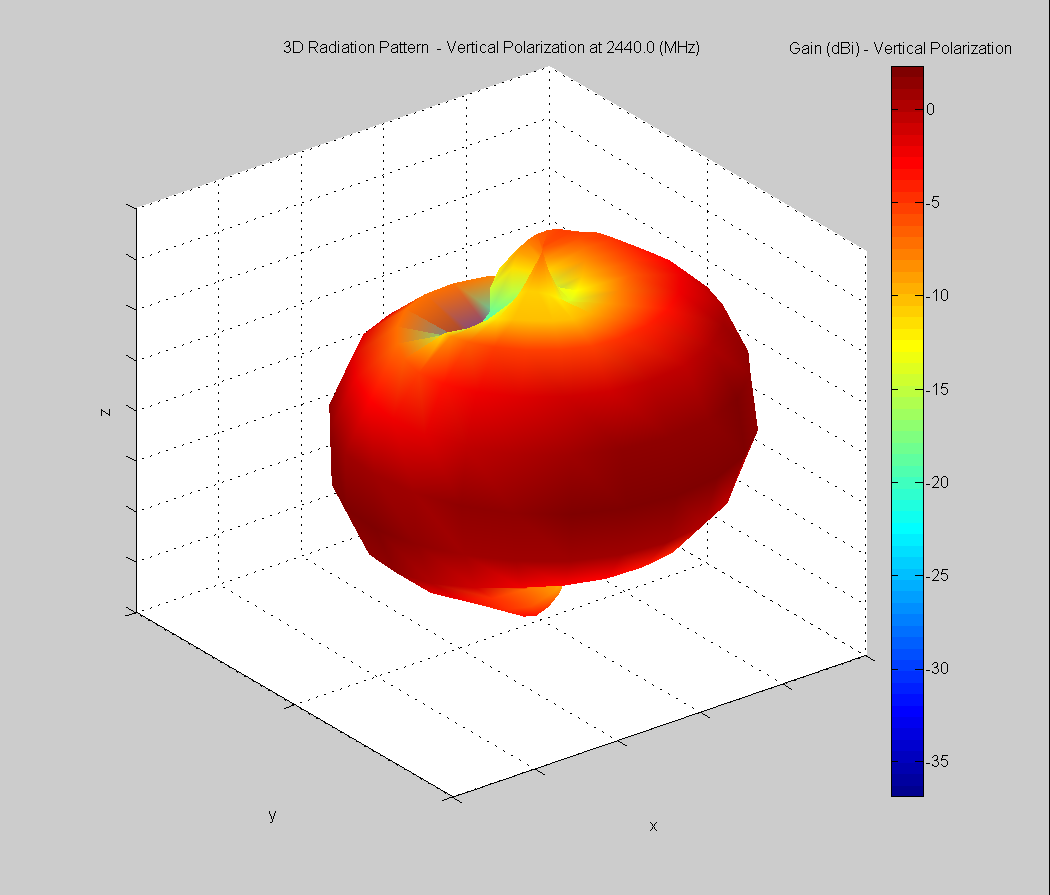
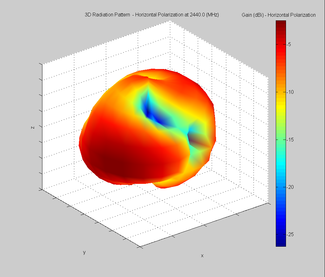
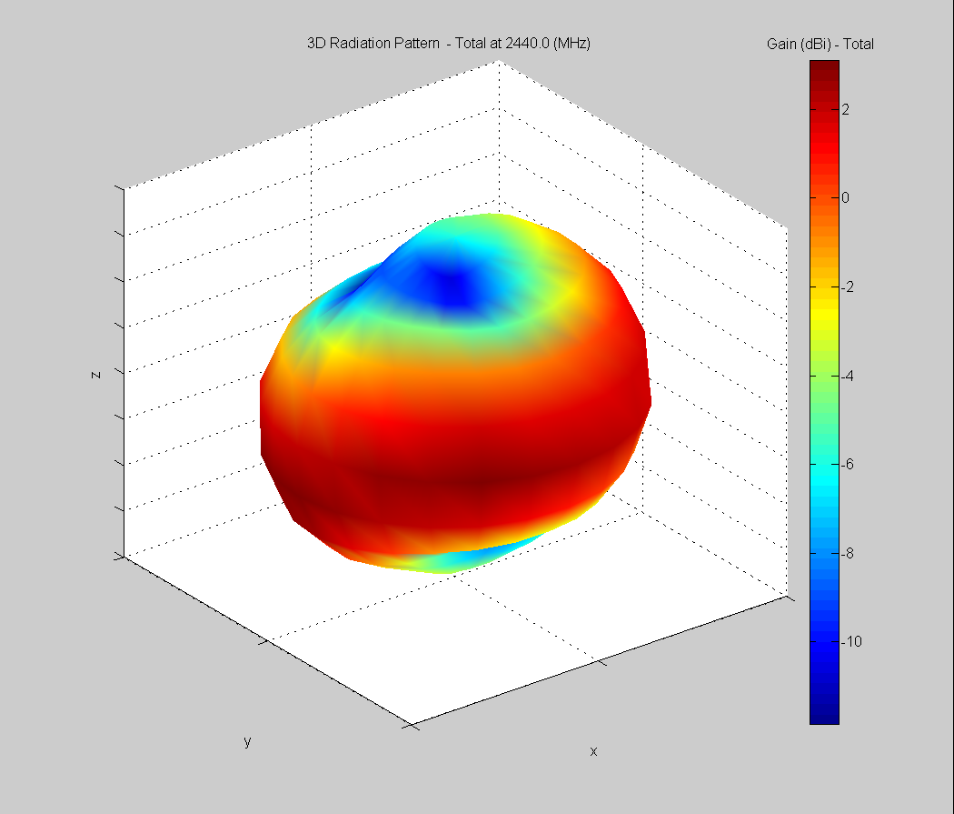
3D Plots at 2440 MHz
 | 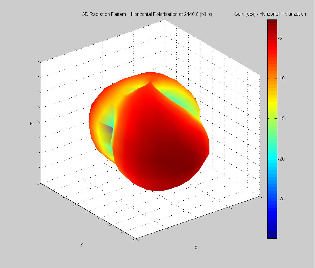 | 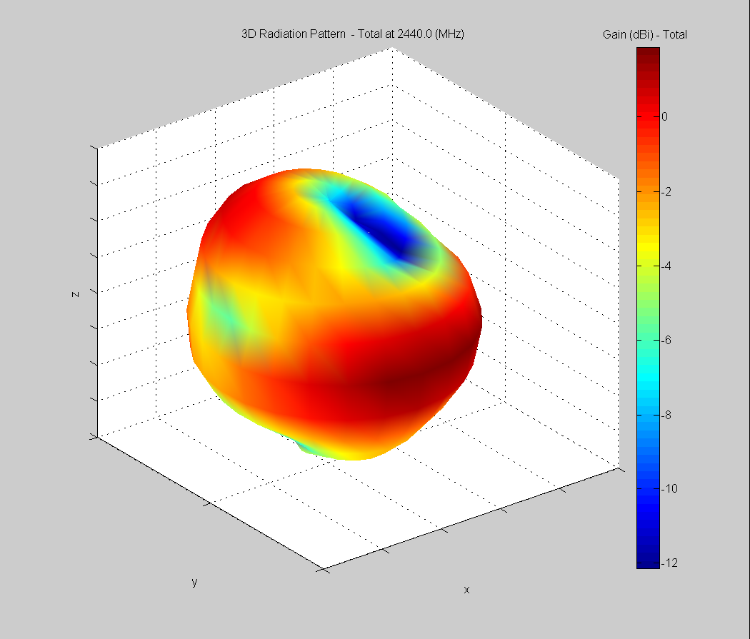 |
| Vertical, horizontal, and total gain plots – 2440 MHz | ||
Azimuthal Conical Cuts at 2480 MHz
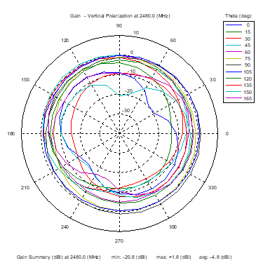 | 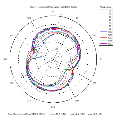 | 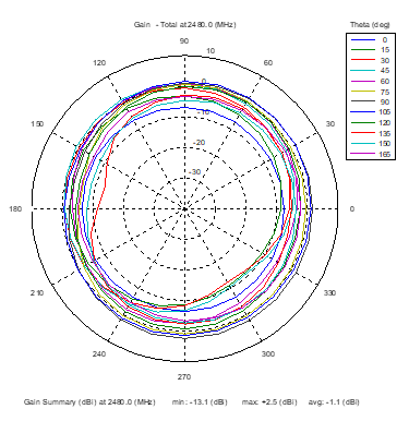 |
| Vertical, horizontal, and total gain patterns – 2480 MHz | ||
3D Plots at 2480 MHz
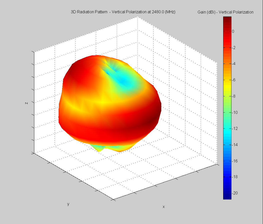 | 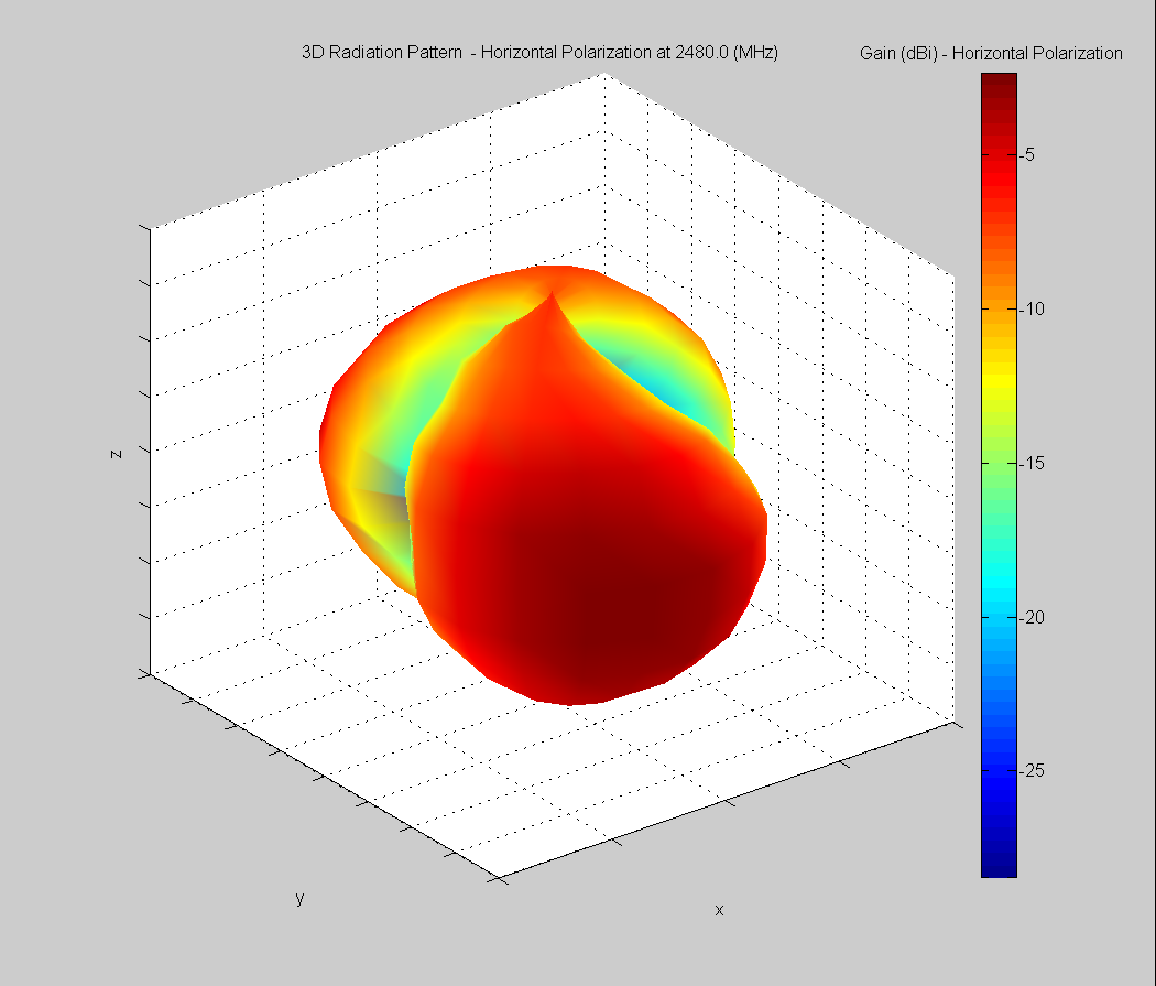 | 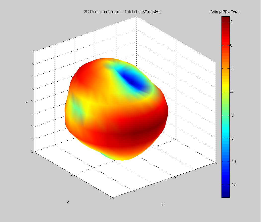 |
| Vertical, horizontal, and total gain plots – 2480 MHz | ||
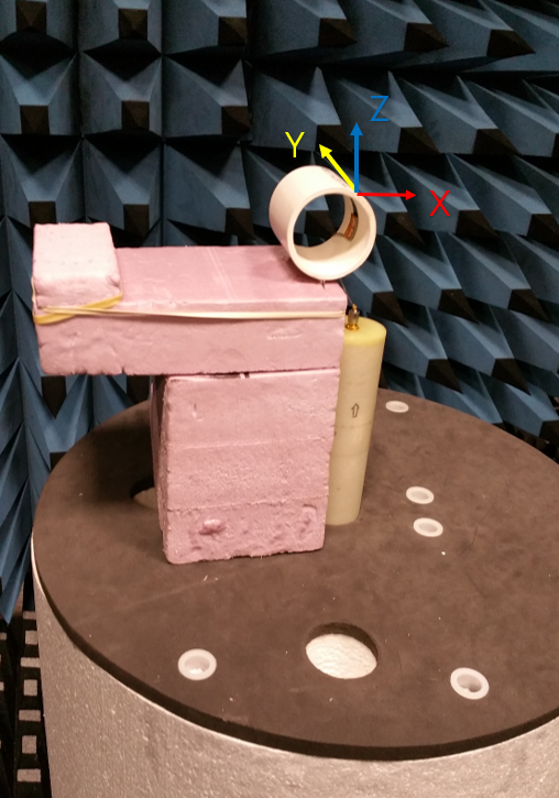
Curved surface Antenna Radiation Performance
FlexPIFA outside 51 mm outer diameter PVC tube
Antenna Measurement Set-Up
Azimuthal Conical Cuts at 2440 MHz
 |  |  |
| Vertical, horizontal, and total gain patterns – 2440 MHz | ||
3D Plots at 2440 MHz
 |  |  |
| Vertical, horizontal, and total gain plots – 2440 MHz | ||
FlexPIFA inside 52 mm inner diameter PVC tube
Antenna Measurement Setup
Azimuthal Conical Cuts at 2440 MHz
 |  |  |
| Vertical, horizontal, and total gain patterns – 2440 MHz | ||
3D Plots at 2440 MHz
 |  |  |
| Vertical, horizontal, and total gain plots – 2440 MHz | ||
Optimal installation Guide
The main element should be kept clear of any non-metal objects (such as plastics) on top of it by at least three millimeters (see below). Similarly, the two long sides of the FlexPIFA should be kept clear of any non-metal object by at least two millimeters (see below). A one-millimeter clearance should be observed from the ground wall to any non-metal object. Mounting the FlexPIFA in a situation that does not allow for these clearance recommendations may change the gain characteristics stated in the datasheet, which could impact overall range of the wireless system.
 | 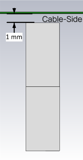 |
| Side Clearance | Ground Wall Clearance |
The ideal material on which to mount the FlexPIFA is 1.5-millimeter thick polycarbonate for maximum performance. However, as previously mentioned, the FlexPIFA can tolerate other non-metallic surfaces and thicknesses and still radiate effectively. Depending on the type of material, the FlexPIFA may be detuned.
The coaxial cable feeding the FlexPIFA should be routed away from the antenna. Do not run the coaxial cable over the top of the FlexPIFA or near the tip of the main element. The cable should be routed perpendicular to the side of the FlexPIFA (this is the way the cable comes assembled) or away from the ground wall. These options are shown below.
Recommended cable routing
 |
 |
As with any antenna, care should be taken not to place conductive materials or objects near the antenna (except as described in the next section). The radiated fields from the antenna induce currents on the surface of the metal; as a result, those currents then produce their own radiation. These re-radiating fields from the metal interfere with the fields radiating from the FlexPIFA (this is true for any antenna). Other objects, such as an LCD display, placed close to the antenna may not affect its tuning but it can distort the radiation pattern. Materials that absorb electromagnetic fields should be kept away from the antenna to maximize performance. Common things to keep in mind when placing the antenna:
- Wire routing
- Speakers – These generate magnetic fields
- Metal chassis and frames
- Battery location
- Proximity to human body
- Display screen – These absorb radiation
- Paint – Do not use metallic coating or flakes
Flex Limits of the FlexPIFA
One of the unique features of the FlexPIFA is its ability to flex. However, due to the adhesive, there are limits as to how much the antenna can be flexed and remain secured to the device. The FlexPIFA should not be flexed in a convex position with a radius less than 16 millimeters. Going smaller than this may result in the antenna peeling off the surface over time. Should a tighter radius of curvature be required, contact Ezurio for assistance.
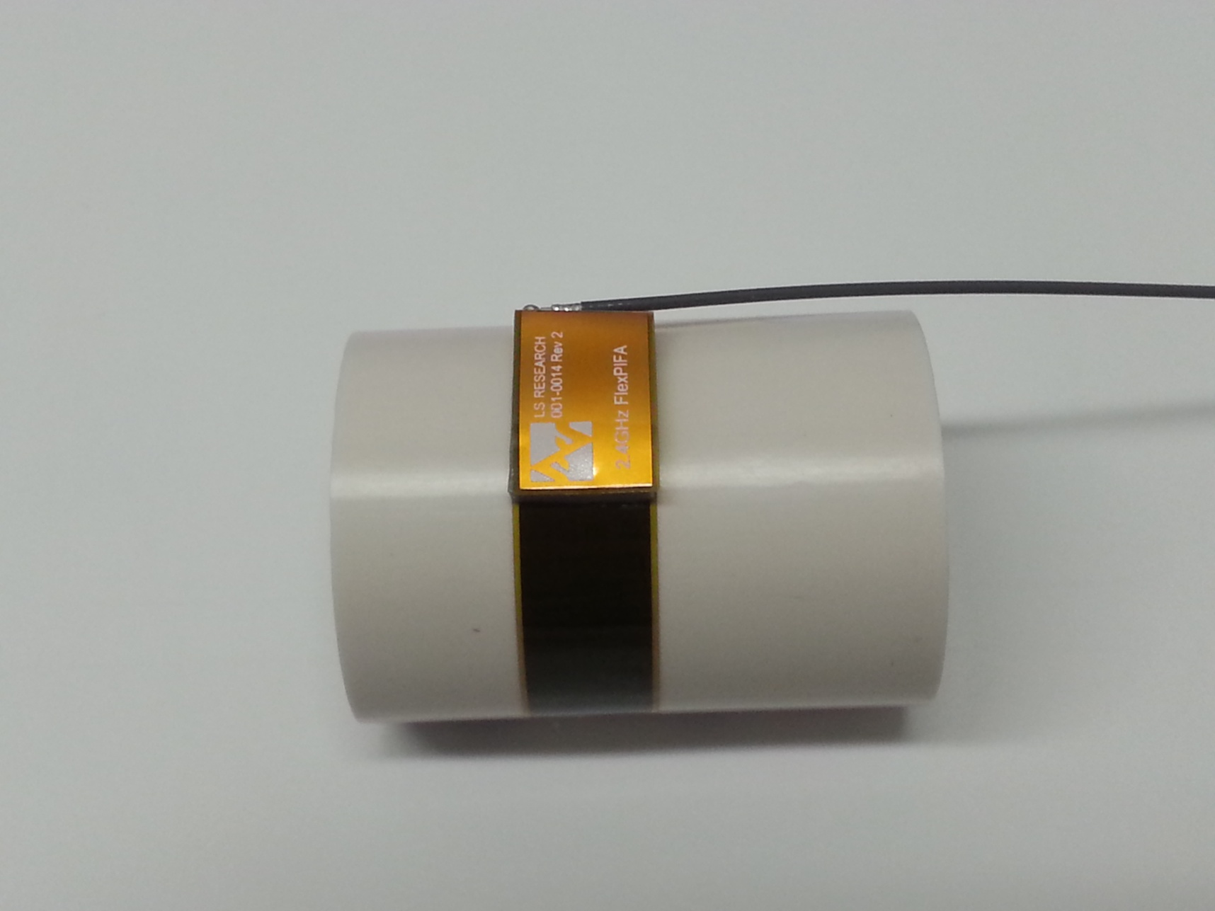
The FlexPIFA should not be flexed in a concave position with a radius less than 25 millimeters. In this scenario, the limiting factor is performance. The ground plate of the antenna is pressed closer to the main element. As previously discussed in the introduction of this datasheet, the fringing fields developing off the end of the element are responsible for most of the radiation. In a concave position with a radius of curvature less than 25 millimeters, the fringing fields are adversely affected, and gain suffers. If a tighter radius of curvature is required, contact Ezurio for assistance.
The FlexPIFA is not designed to be twisted or crumpled. The adhesive back should lay flush with the surface on which it is mounted.
Mounting on Metal and Body Loaded Applications
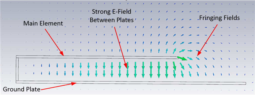
The FlexPIFA can tolerate being mounted on conductive surfaces. There will be some detuning of the antenna, which translates into some gain reduction. Even though the FlexPIFA is optimized to work on non-metallic surfaces, it still radiates efficiently due to the fringing fields (see e-field diagram at the beginning of Optimal Installation Guide). The ground plate of the FlexPIFA carries the adhesive backing; placing the antenna onto a metal surface simply enlarges the size of the ground beneath the main element. Previously, the fringing fields only interacted with the small ground of the FlexPIFA, however they are now interacting with the much larger ground. The fringing fields still develop and radiate, but the antenna will no longer tune as well to the 2.4 GHz frequency band. Consequently, the VSWR increases and there is some loss in radiated power. If the FlexPIFA cannot meet your range requirements after being implemented on a metal surface, contact Ezurio for a custom antenna build to help meet your application needs.
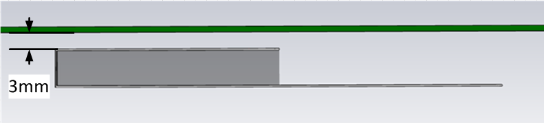
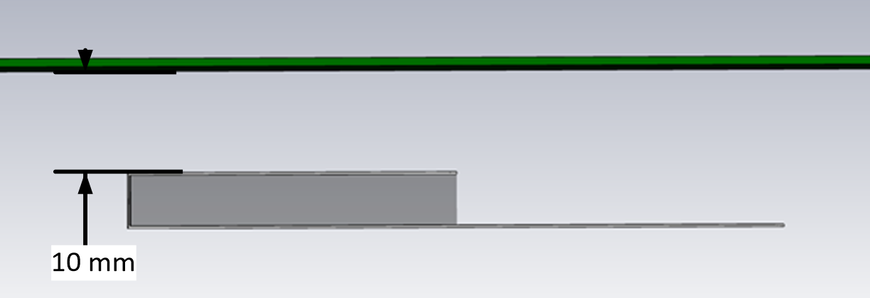
Do not mount the FlexPIFA where metal is within ten millimeters above the main element (see the following two images). Not only does this severely limit the radiation pattern (mainly due to the re-radiation problem previously described) it detunes the antenna inside of this range.
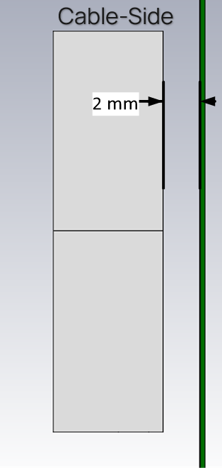
Similarly, the two long sides of the FlexPIFA should be kept clear of any metal object by at least five millimeters. These keep out requirements pertaining to conductive materials only and are different from those listed in the previous sections which apply to non-conductive materials. In general, it is good practice to always keep metals as far away from the antenna as possible.
For the best performance, a spacer should be placed between the FlexPIFA and the conductive surface (see below). The spacer should be 1.5 millimeters thick polycarbonate. This will significantly improve performance and tuning of the FlexPIFA on a metal surface. Other non-conductive materials such as ABS plastic can be used; however, polycarbonate provides the best results.
For body-worn applications, the FlexPIFA can tolerate the presence of the human body. We do not recommend that you mount the antenna directly on body tissue to avoid detuning the FlexPIFA.
Additionally, the human body is an excellent absorber of 2.4 GHz RF signals. As a result, expect a reduction in range due to the presence of a body. In a body-worn application, the ground plate of the FlexPIFA should be closest to the body tissue. The main element should be pointed away from the body. Additionally, for handheld devices, the FlexPIFA should be mounted in a location where it is not covered by the hand. If the antenna is mounted in a location where the main element is covered or near a human body, ensure that there is at least a ten-millimeter separation distance between the main element and the body as shown above.
Additionally, when the FlexPIFA is mounted very close to body tissue, use a spacer to create separation distance between the body tissue and ground plate. This ensures maximum performance and prevents the antenna from detuning. As previously mentioned, the ideal spacer material is 1.5 mm thick polycarbonate.
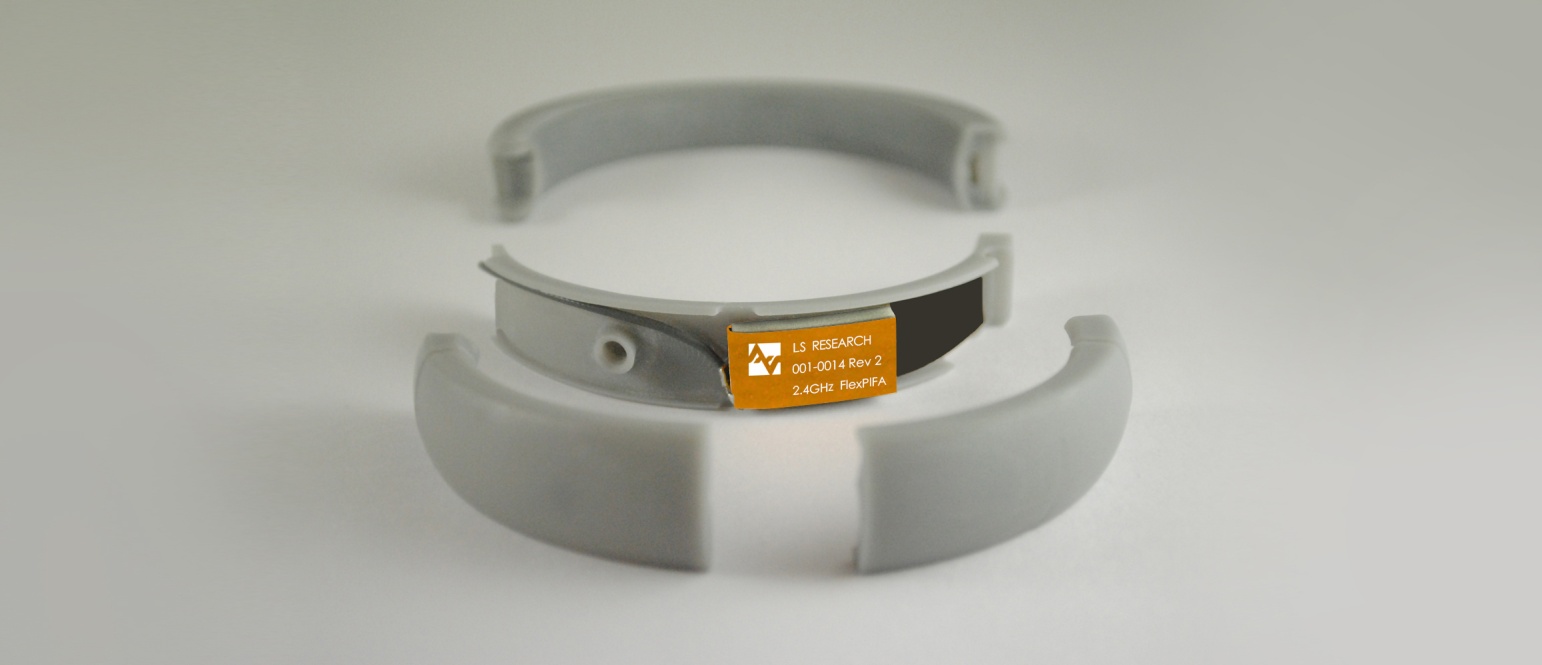
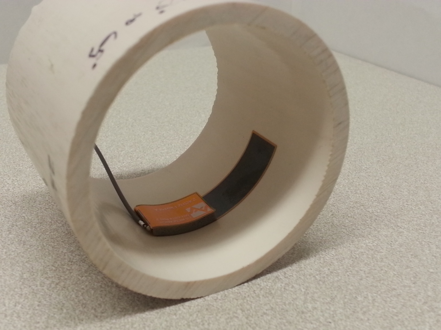
Quite often this separation distance between the body tissue and the FlexPIFA is already provided by the enclosure. Below is an example of a bracelet with the FlexPIFA integrated inside it. The enclosure provides enough spacing between the antenna and body tissue to prevent any major detuning. The enclosure is made of polycarbonate.