/filters:background_color(white)/2024-10/i-FlexPIFA-21.4-EFG2400A-view3.png)
Features and Benefits
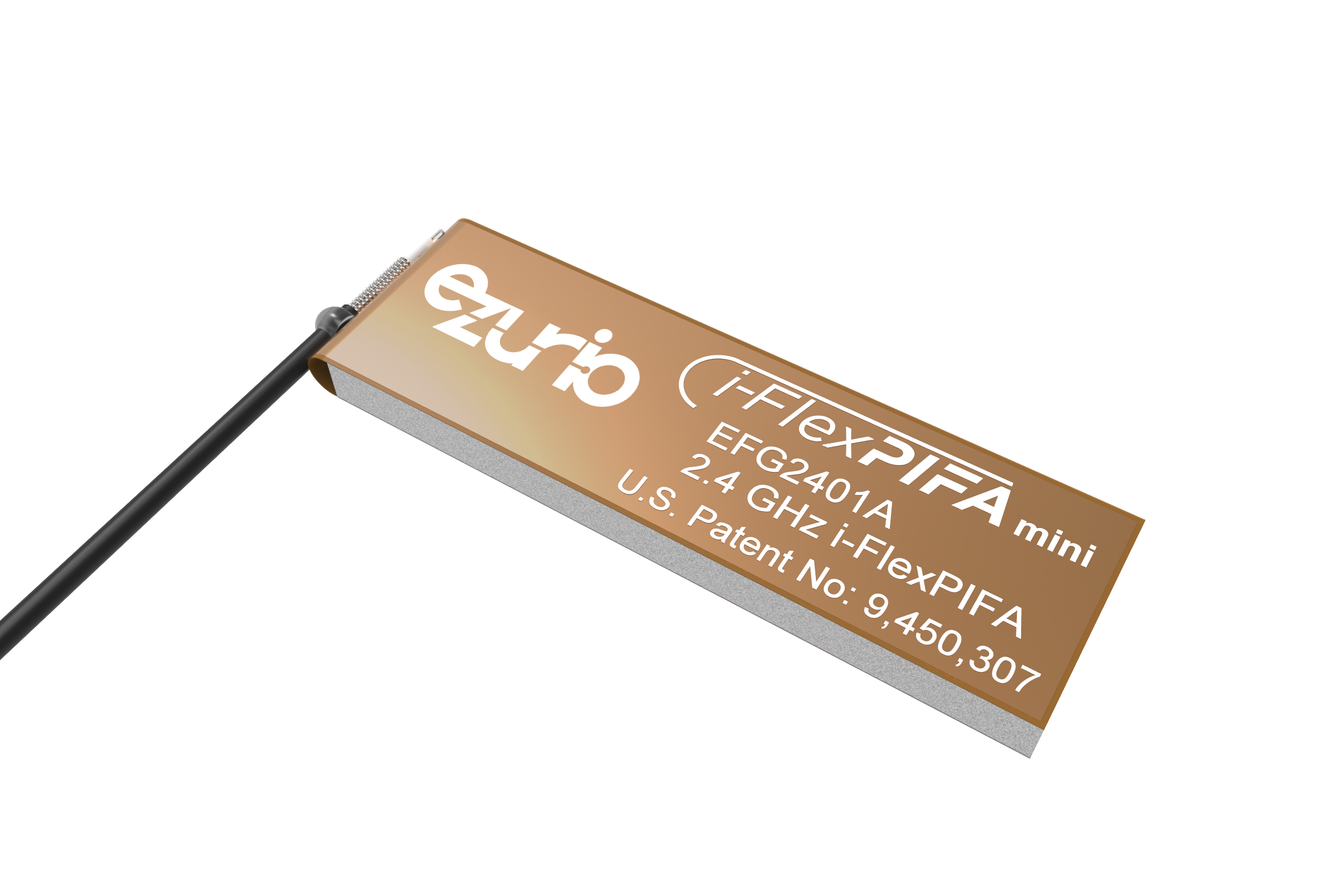
- Quick and easy installation
- Smallest form factor i-FlexPIFATM
- Adhesive holds to surface during humidity exposure and hot/cold cycles
- RoHS-compliant
- Radiation direction maximized on adhesive side for outward-facing orientation
- Patent Number: 9450307
- Can be installed in the following ways:
- On different non-conductive surfaces and thicknesses
- On flat or curved surfaces
- MIMO array element
- On the front or top face of an enclosure interior (alternative placement to FlexPIFA)
| Specifications | |
|---|---|
| Frequency (MHz) | 2400 - 2480 |
| Peak Gain (dBi) | +2.0 |
| Average Efficiency (dB) | > -2.5 |
| VSWR (MHz) | < 2.5:1 |
| Impedance (Ω) | 50 |
| Polarization | Linear |
| Mechanical Specifications | |||||
|---|---|---|---|---|---|
| Antenna Type | Inverted Ground Flexible Planar Inverted F Antenna (i-FlexPIFA) | ||||
| Dimensions – mm (inches) | 35.9 x 11.0 x 2.9 (1.41 x 0.43 x 0.114) | ||||
| Weight – g (oz.) | 1.10 (0.039) | ||||
| Color | Clear yellow | ||||
| Adhesive | 3M 100MP | ||||
| Connector Mating Height (max) – mm |
| ||||
| Environmental Specifications | |
|---|---|
| Operating Temperature – °C (°F) | -40 to +85°C (-40 to +185°F) |
| Material Substance Compliance | RoHS |
Configuration
| Part Number | Cable Length | Connector |
|---|---|---|
| EFG2401A3S-10MHF1 | 100 mm | MHF1 |
| EFG2401A3S-10MH4L | 100 mm | MHF4L |
Note: Specifications are based on the 100mm cable length, standard antenna version with MHF1 / U.FL connector. Varying the cable length or type or connector will cause variations in these antenna specifications.
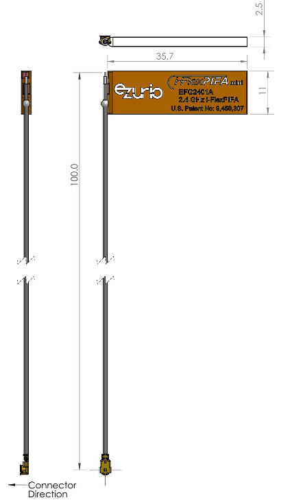
Mechanical Drawing
Physical Dimensions (in mm) of the EFG2401A with a 100mm Long Cable
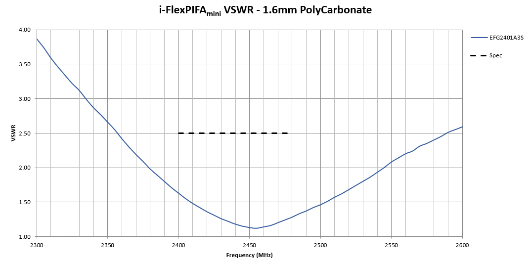
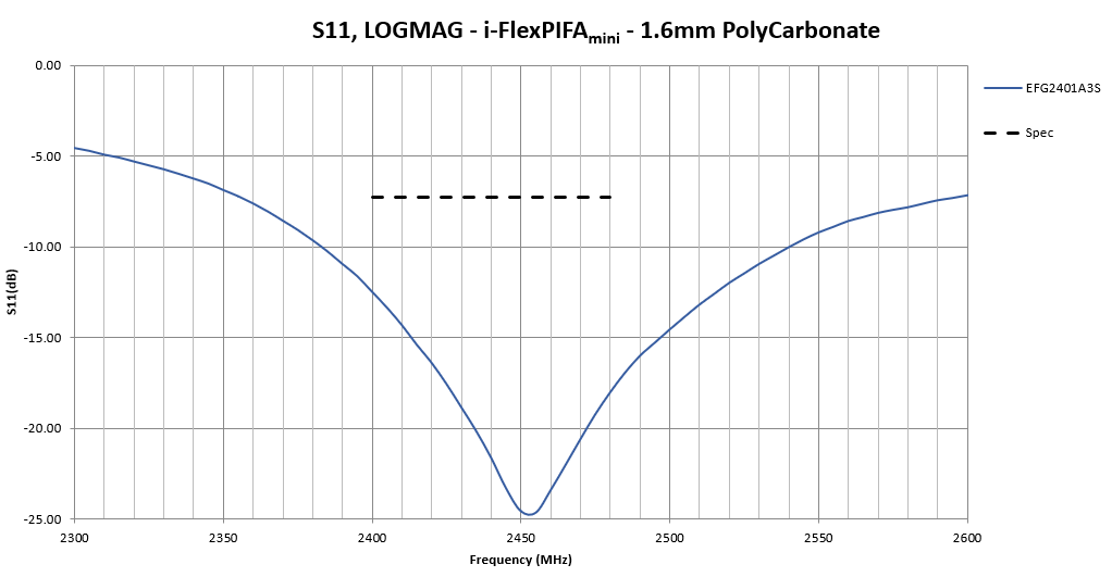
Flat Surface Antenna Measurements
Flat surface measurements were performed with the antenna centered on a 1.6 mm-thick plate of polycarbonate.
VSWR
Return Loss
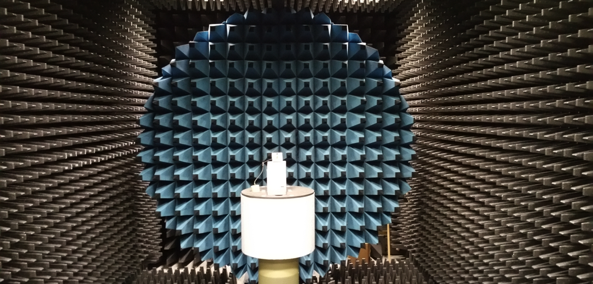
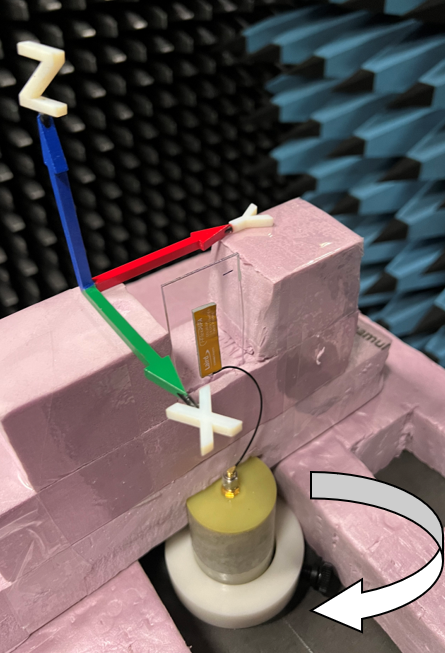
Antenna Chamber Test Setup
Antenna measurements such as VSWR and S11 were measured with an Agilent E5071C vector network analyzer. Radiation patterns were measured with a Rohde & Schwarz ZNB8-4PORT vector network analyzer in a Howland Company 3100 chamber equivalent. Phase center is nine inches above the Phi positioner.
Antenna Radiation Performance
FlexPIFA centered on a 1.6 mm-thick plate of polycarbonate
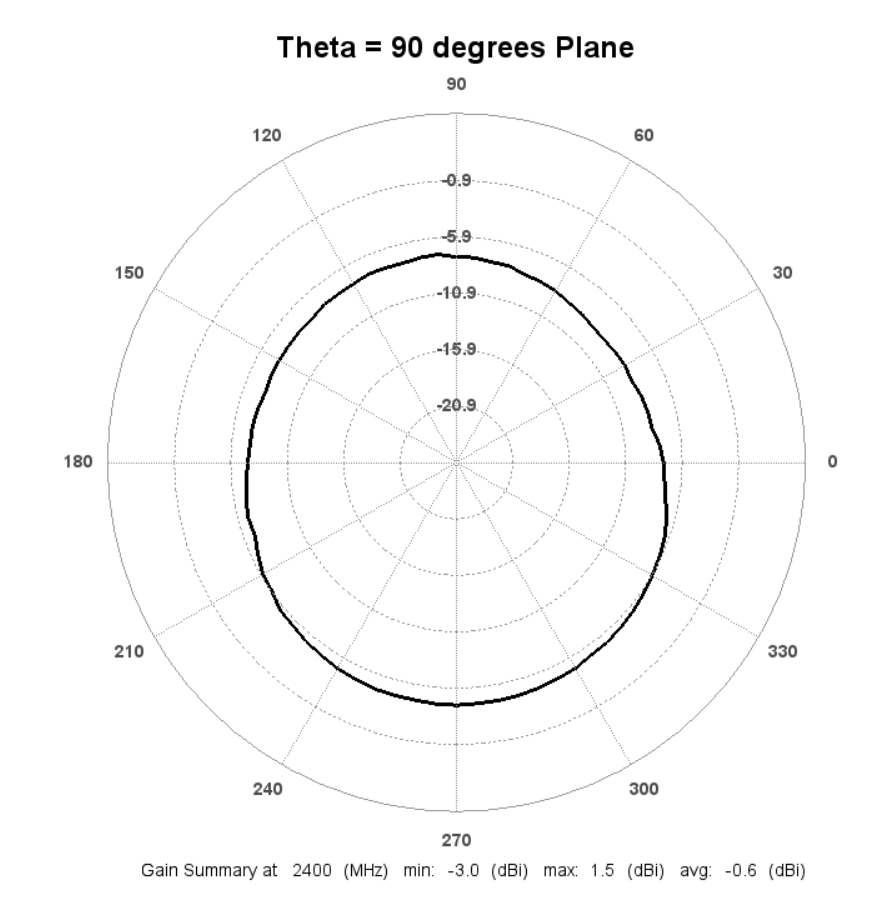
Radiation Patterns – 2D Plots
2D Plots at 2400 MHz
 | 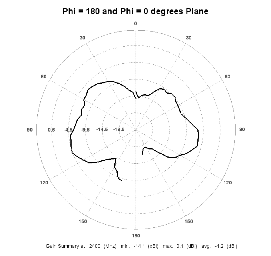 | 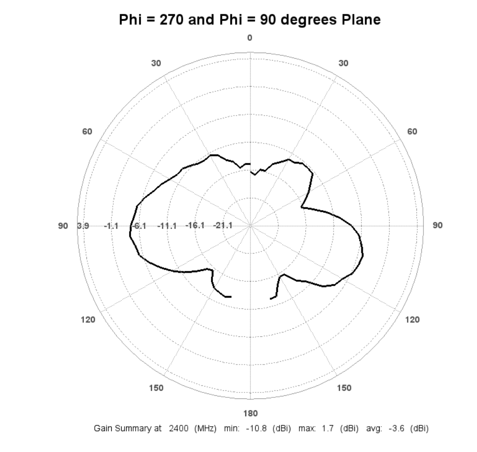 |
2D Plots at 2440 MHz
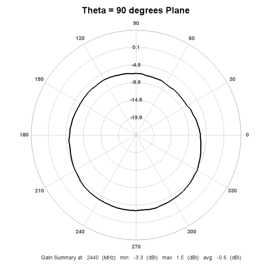 | 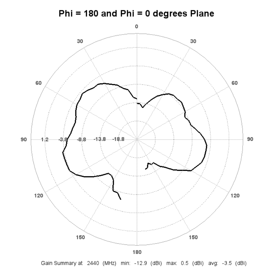 | 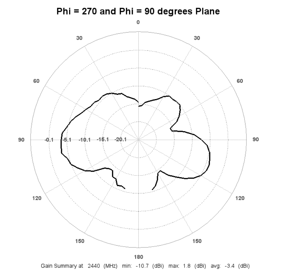 |
2D Plots at 2480 MHz
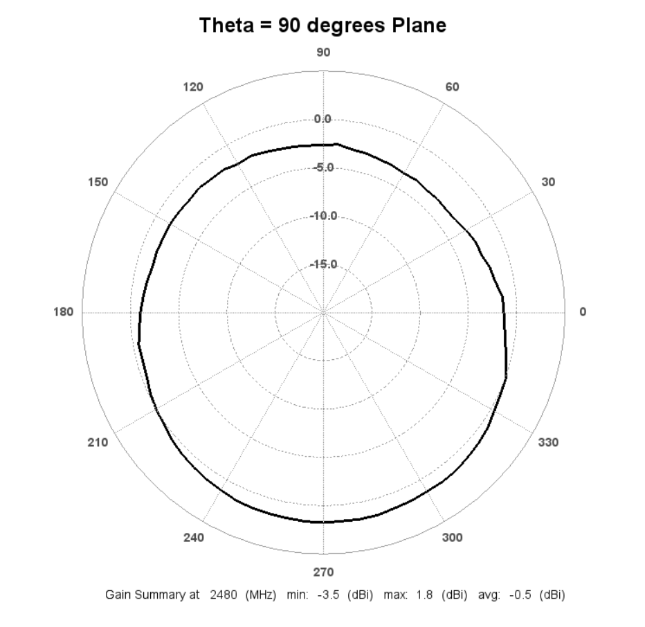 | 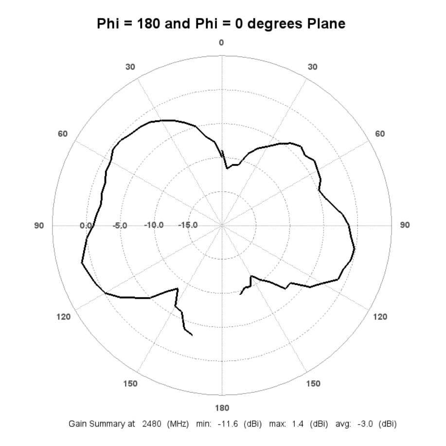 | 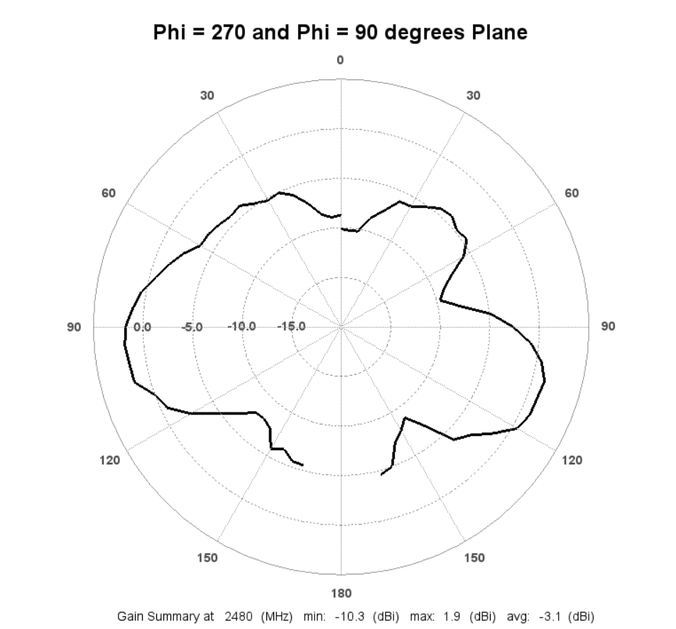 |
Radiation Patterns – 3D Plots
3D Plots at 2400 MHz
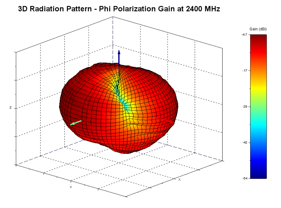 | 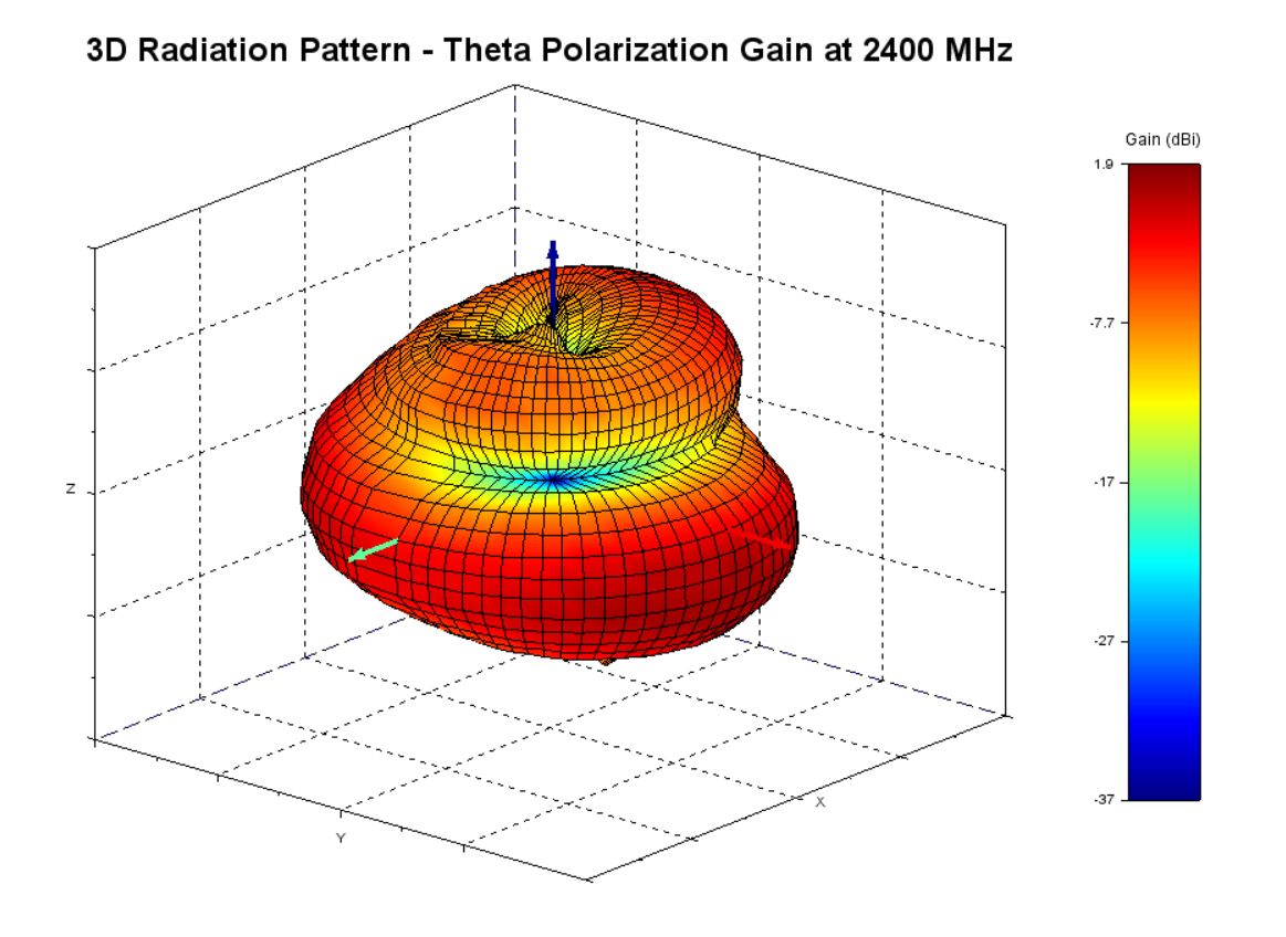 | 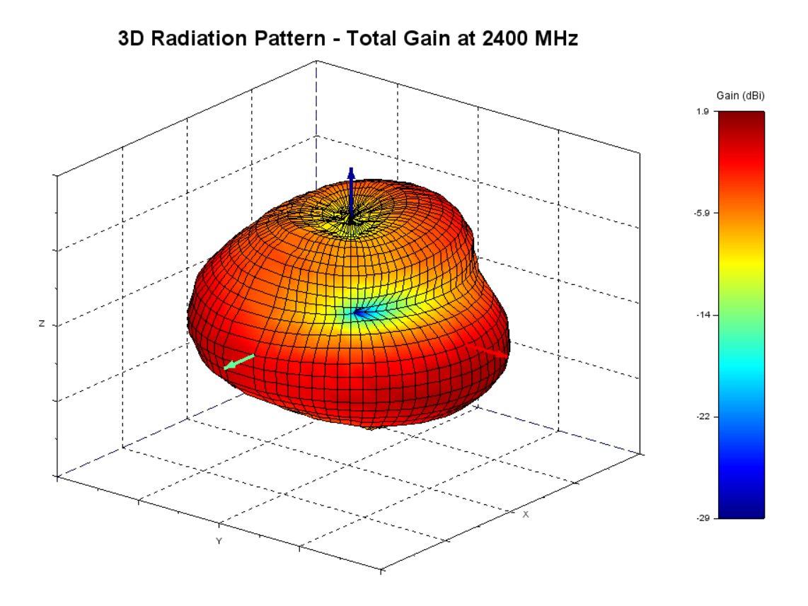 |
| Phi polarization, Theta polarization and, and total gain plots – 2400 MHz | ||
3D Plots at 2440 MHz
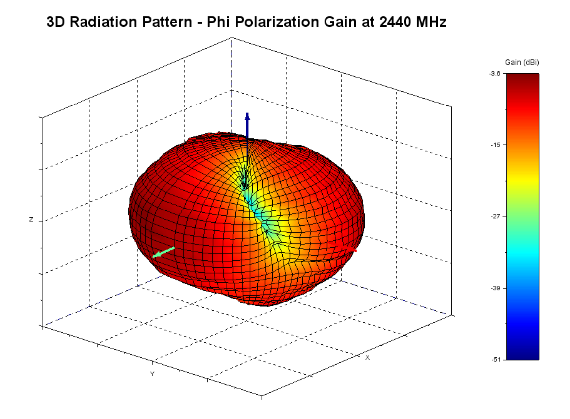 | 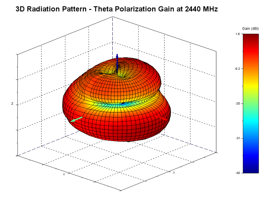 | 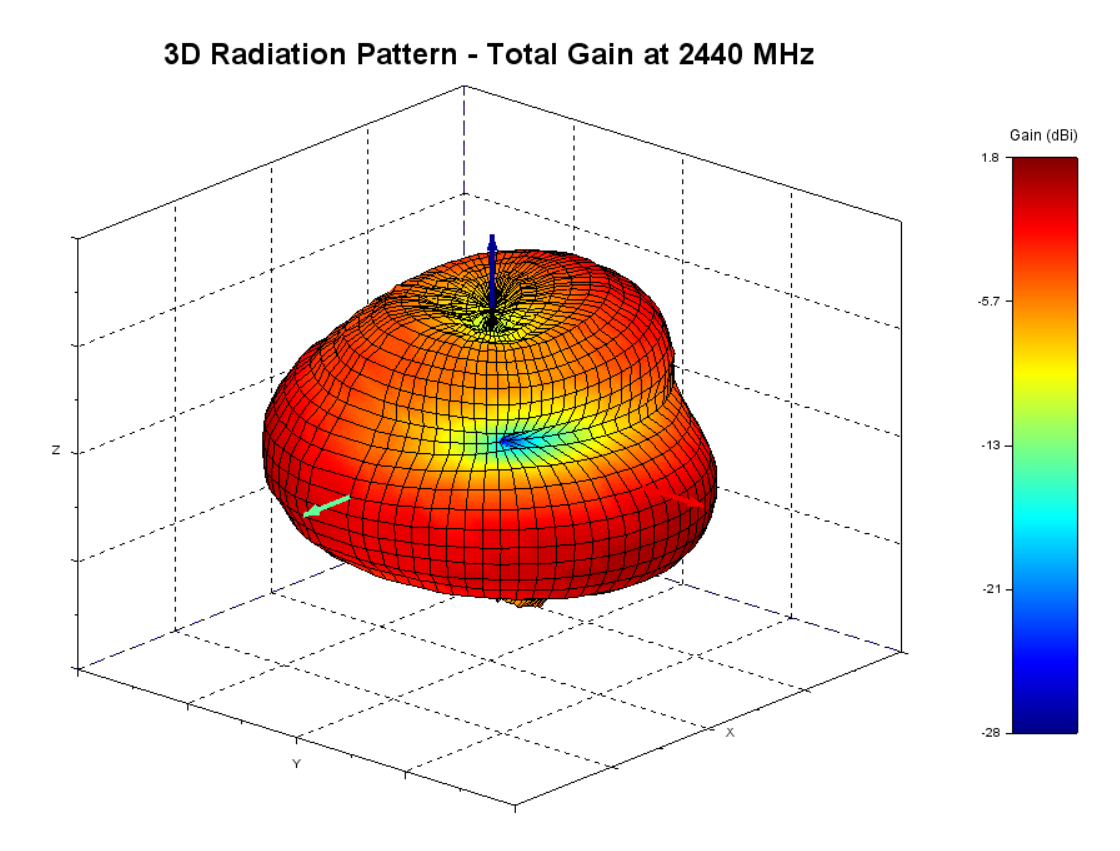 |
| Phi polarization, Theta polarization and, and total gain plots – 2440 MHz | ||
3D Plots at 2480 MHz
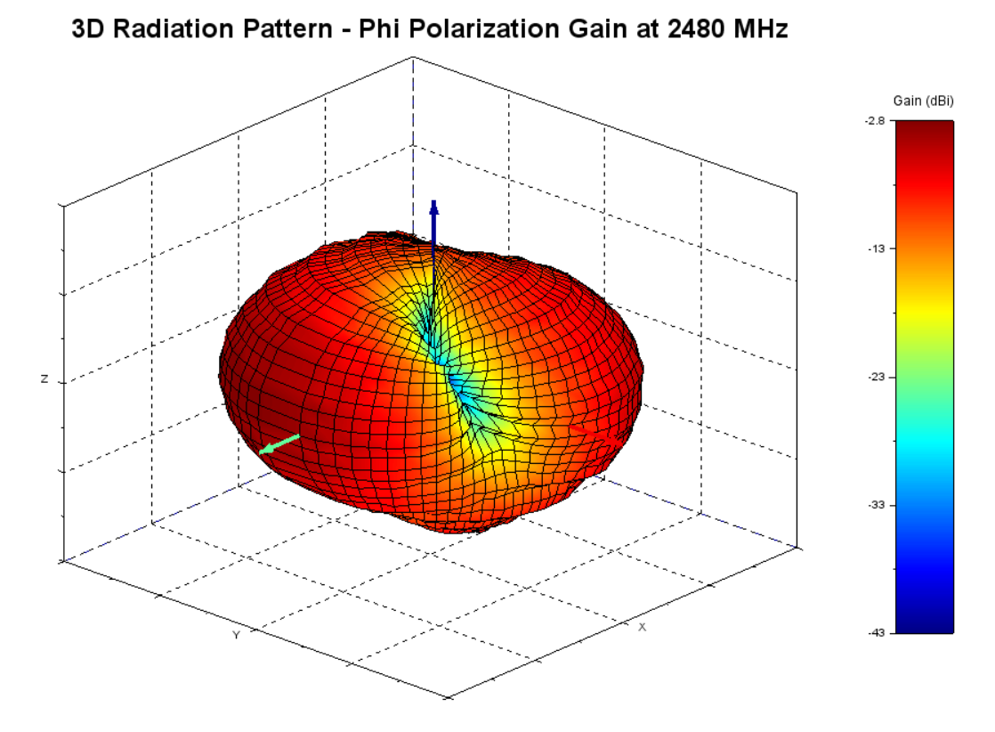 | 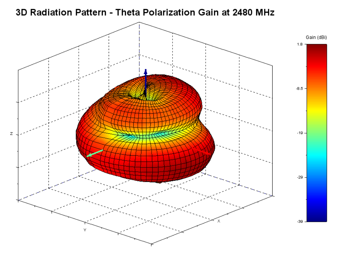 | 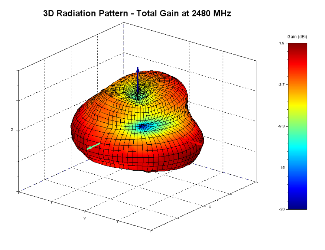 |
| Phi polarization, Theta polarization and, and total gain plots – 2480 MHz | ||
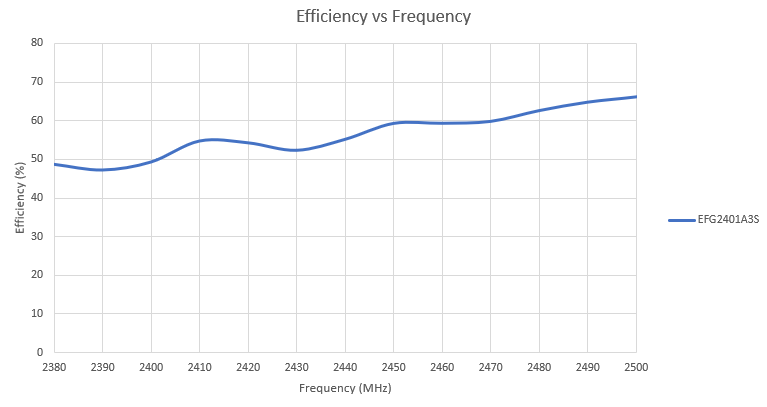
Efficiency
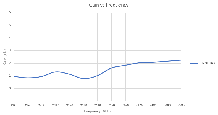
Antenna Gain
Total Gain vs. Frequency (as per IEEE definition)
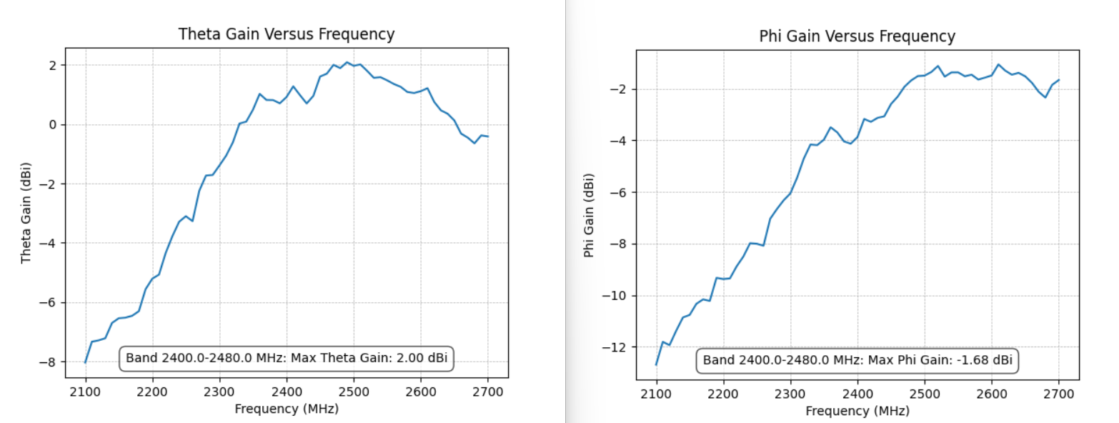
Peak Gain from Theta and Phi Polarization vs. Frequency
Antenna Placement & Keep Out Region
Antenna Placement
The i-FlexPIFA is designed to be attached to dielectric surfaces encountered in plastic packaging of wireless communications devices. The nominal attachment surface used in its design and characterization is an 80 mm x 40 mm, 1.6-millimeter thick, Polycarbonate sheet.
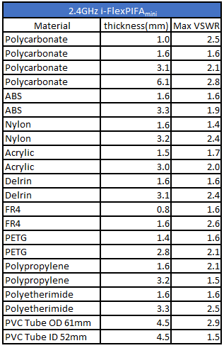
The VSWR of the i-FlexPIFAmini is shown below for the following materials and thicknesses outside of these specifications:
Antenna Conductive Material Keep Out Region
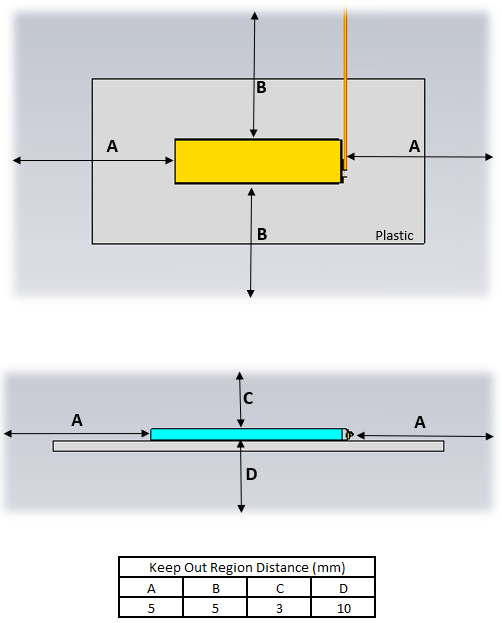
Notes:
- Antenna is designed to be mounted on polycarbonate with a nominal thickness of 2.25mm (1.5mm - 3mm)
- Diagram is not to scale
Product Labeling History
Rev 2.0 - Initial Production Release
Legacy - Revision History
| Version | Date | Notes | Approver |
|---|---|---|---|
| 0.1 | 16 Nov 2023 | Preliminary Release | Adam Engelbrecht |
| 1.0 | 8 Apr 2024 | Initial Release | Adam Engelbrecht |
| 2.0 | 14 Aug 2024 | Ezurio rebranding | Dave Drogowski |