/filters:background_color(white)/2024-12/Sterling-EWB-AT-Command.png)
Programming with WICED on Windows
Sterling EWB - Programming with WICED on Windows
This tutorial shows how to get the Laird Sterling EWB DVK setup for programming with WICED via USB JTAG or External JTAG on a Windows PC.
Required Items
Hardware Required
Two different development kits are available with part numbers supporting two different antenna types.
- DVK 455-00030 Chip Antenna
- DVK 455-00031 External Antenna
Additional items needed:
- 4.4-10V Power Supply
- TTL-232R-3v3 cable
- USB cable - Type A to micro type B (included in DVK kit)
- JLink Plus
Software Required
Software is provided by Infineon/Cypress based off Eclipse which is called WICED. WICED can be download from the link below. It must be installed in a shorter path without spaces to prevent pathing issues than the default pathing provided by WICED. Example of a short path without spaces for windows is C:\WICED-Studio-6.6.
Documentation
Documentation for the Laird DVK is available on the Laird Sterling EWB. This includes product briefs, datasheets, guides, certifications, technical drawings, software, and application notes.
Hardware Setup
The Sterling EWB has a lot of flexibility when it comes to powering, IO interface, JTAG, etc. The board was designed with the use of USB JTAG in mind and when an external JTAG was added to the board it was unknown how the USB JTAG and external JTAG would work well with each other. What has been found is the FTDI USB interferes with the external JTAG and a hardware modification is required. This can be seen below with the added switch tied to the FTDI U8/14 to ground at the leg of SW4. The switch allows for being able to switch between USB JTAG and external JTAG. It's recommended to use one or the other, using both at the same time could potentially damage one of the JTAG interfaces.
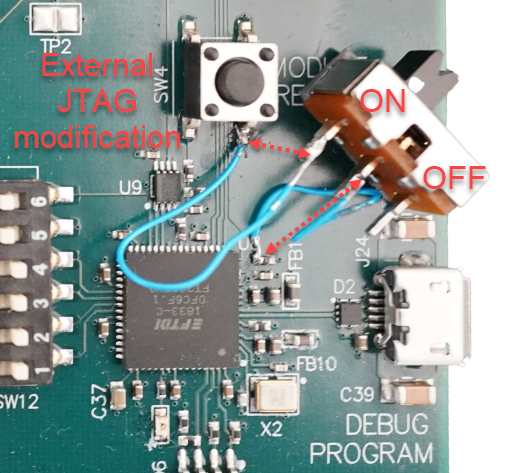
Hardware modification
Below is an example of the hardware modification. With the switch set to ON it's completing the circuit from U8/14 on the FTDI side to the GND leg of SW4. If desired a wire could be ran between leaving out the switch and making only the external JTAG available. This modification puts the FTDI chip into RESET preventing any conflict between the USB JTAG and external JTAG.
Physical view of hardware modification:
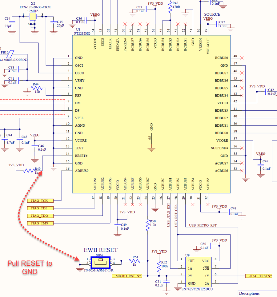
Schematic view of hardware modification:
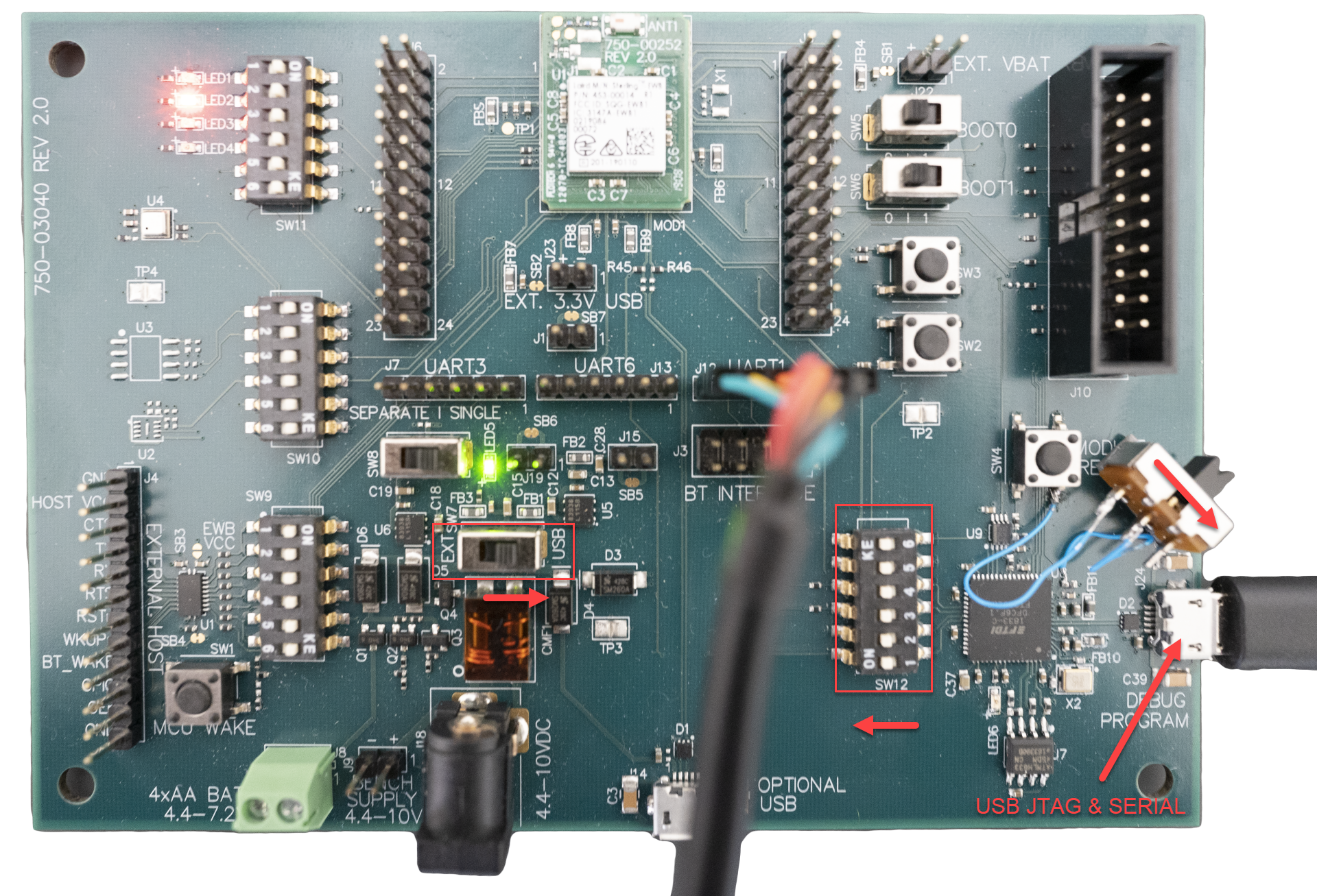
USB JTAG
The USB1 Debug/Program Interface is the default JTAG interface. Software can be downloaded and debugged via this interface.
- Set SW12 all to ON
- Set SW7 to USB
- If hardware modification is in place ensure switch is off (not connecting U8/14 to GND)
External JTAG
The external JTAG (J10) can be used to program and debug with the hardware modification in place.
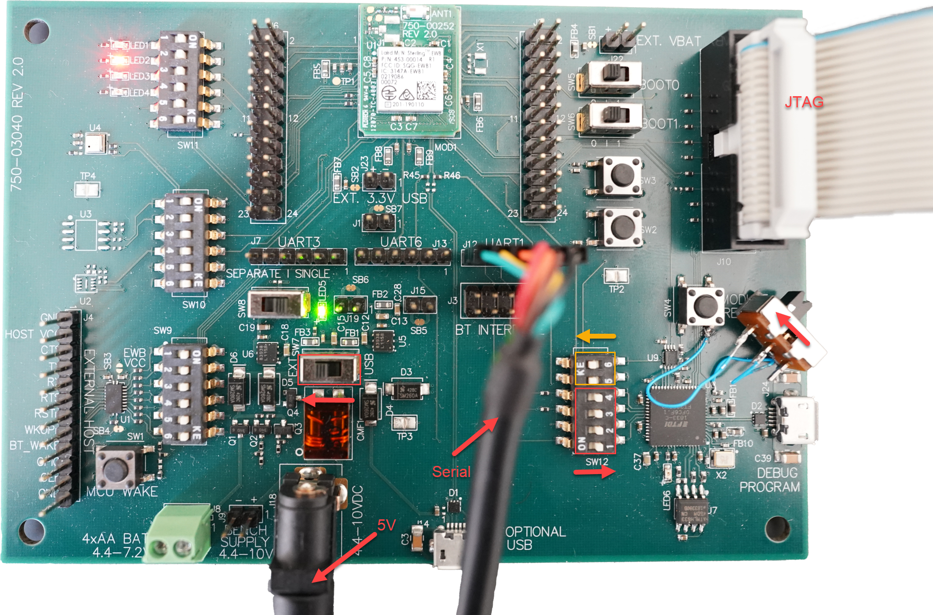
*Note using the external JTAG does disable the UART connection on the debug/programming USB1 connector. Please use UART1 (J12) for a serial interface for debugging. Do not use both USB JTAG and external JTAG at the same time to prevent damage.
Software Setup
The Sterling can be used either with AT Commands or Programmed with WICED. This tutorial will cover Programming with WICED as the AT commands are well documented.
AT Commands
Programming with WICED
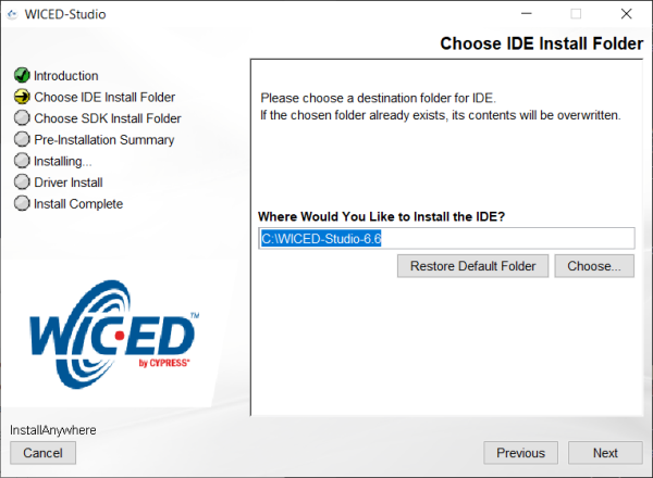
Setup
-
Install the IDE into a short path as this will prevent any pathing issues with folders with spaces in them.
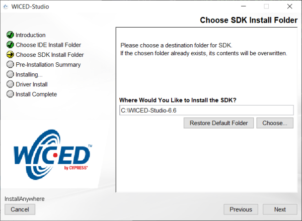
-
Install the SDK into the same path for easy of use and to avoid any pathing issues with folders with spaces in them.
-
From here the install is straight forward, finish the install.
-
The jlink configuration needs adjusted. Edit the following file "C:\WICED-Studio-6.6\43xxx_Wi-Fi\tools\OpenOCD\jlink.cfg" shown below. If you've elected to install the SDK in a different location then this file will be located accordingly.
interface jlink reset_config trst_and_srst srst_open_drain -
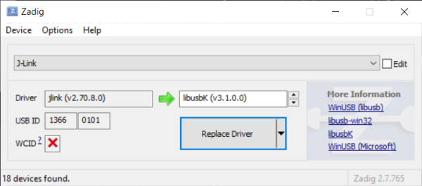
The driver that WICED is using in this walk-thru is libusbk and can be installed using Zadiag generic USB drivers. If Jlink drivers are installed then when in Zadiag set the following to install generic libusbk driver.
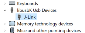
When using the Jlink Plus with the libusbk driver installed the device manager will look like:
-
Download the example demo at https://github.com/LairdCP/ewb_wiced_demo and extract the contents of "43xxx_Wi-Fi" folder to "C:\WICED-Studio-6.6\43xxx_Wi-Fi". This provides an example but also platform specific files.
If you want to use the Laird demo follow the instructions on the ewb_wiced_demo github to download the rest of the components.
-
Now that platform specific files for the LAIRD_EWB are installed a make target can be created for the desired example. For example snip.apsta make targets would be:
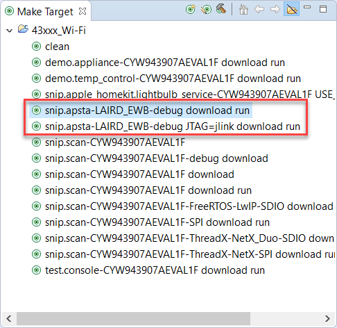
-
USB JTAG make target will be:
snip.apsta-LAIRD_EWB-debug download run -
External JTAG make target will be:
snip.apsta-LAIRD_EWB-debug JTAG=jlink download runNote the -debug is needed for debugging
-
Troubleshooting WICED
If the target fails to download ensure the hardware is setup correctly. Next make sure to use the correct make target for the JTAG interface being used.
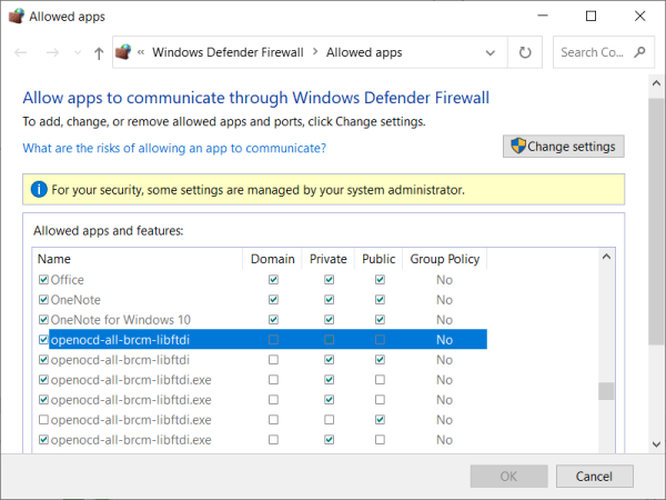
If this is the first time running WICED and downloading to target then a window should popup asking for firewall access for the openocd-all-brcm-libftdi.exe. If this popup doesn't appear then this can be fixed either by manually editing the firewall or running the openocd-all-brcm-libftdi.exe. Manually running the openocd-all-brcm-libftdi.exe file is the easiest way to add these to the firewall.
Firewall settings for OpenOCD
Firewall settings should look similar to:
Manually running OpenOCD
To manually run the openocd-all-brcm-libftdi.exe file go to folder "C:\WICED-Studio-6.6\43xxx_Wi-Fi\tools\OpenOCD\Win32\openocd-all-brcm-libftdi.exe" and double click on it. This should bring up the dialog box to allow for firewall access. If not this will have to be added manually. If the rules can't be added manually then you may need to contact your system administrator.
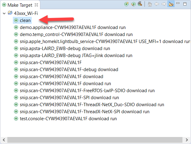
make clean
When switching projects or JTAG interfaces it's best practice to do a clean from the make target selection:
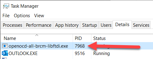
openocd already running
Occasionally a download will still fail and this could be due to openocd-all-brcm-libftdi.exe already running in the background. Check the Task Manager to ensure openocd-all-brcm-libftdi.exe isn't already running or running multiple times. Close any process of openocd-all-brcm-libftdi.exe and try downloading again.
Debugging
Using the external JTAG the application is downloaded to target debugging can be started by:
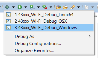
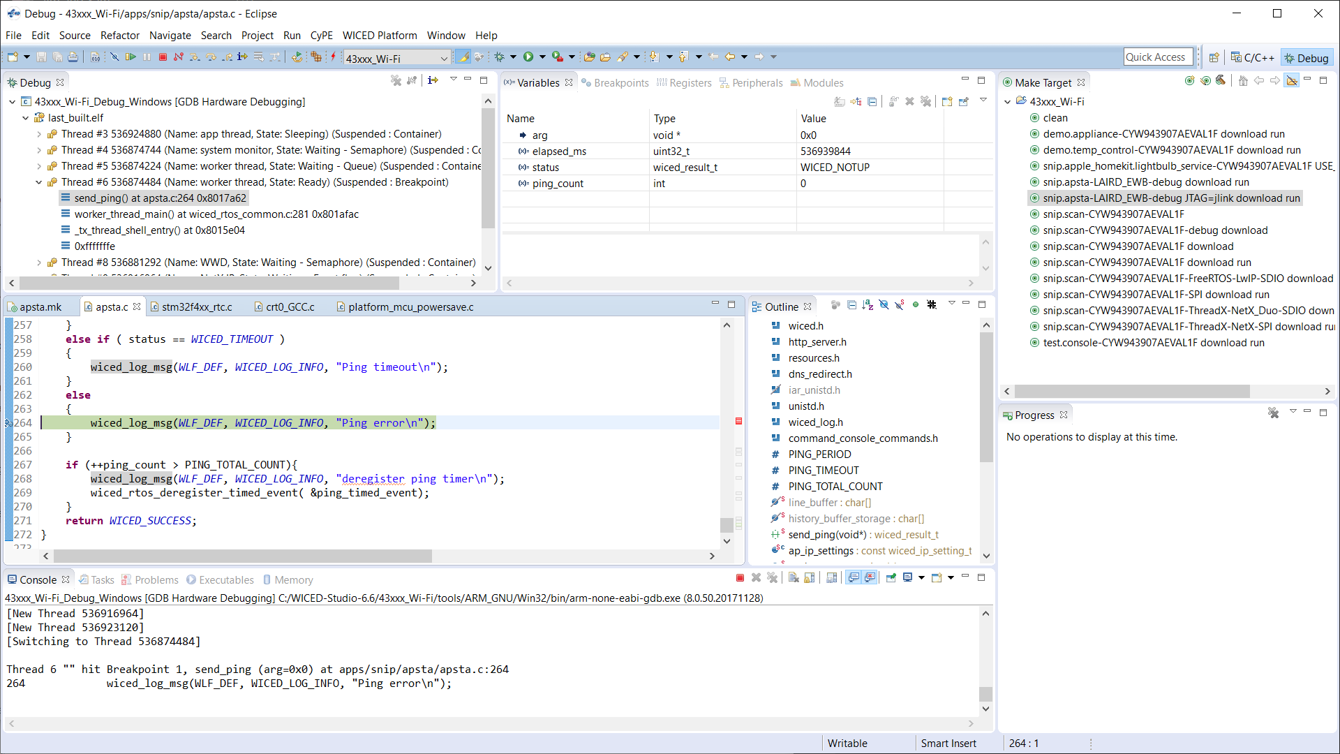
Once in debugging and running, then add breakpoints. Below you can see a stop at breakpoint and variables values.
Additional Information and Support
- Sterling-EWB Product Page
- Sterling-EWB Documentation
- Sterling-EWB FAQs
- Sterling-EWB Demo on GitHub
- Laird Support (scroll to bottom of page and select Open a Support Ticket)
Sending MQTT Messages to AWS
Sending MQTT Messages to AWS using AT Command Firmware
This tutorial will show you how to connect the Sterling EWB to an Access Point and then send MQTT messages to AWS.
Required Tools
- EWB dev kit (Part No. 455-00030 or 455-00031)
- TTL-232R-3V3 USB to UART Cable
- Windows PC
- WiFi Access Point
Prerequisites
-
You have flashed the AT Command Firmware into the Sterling EWB dev kit. To flash the firmware, simply download it from our website, connect to J24 of the dev kit, and then run the flash_AT.bat file included with the firmware.
-
You have an AWS account with IoT Core Service.
-
You have a Windows PC with Python 3.x.x installed. This demo was done with v3.9.1
-
You have downloaded the ATCommands_SampleApps from our website.
-
You have a WiFi access point to connect to the cloud.
Setup
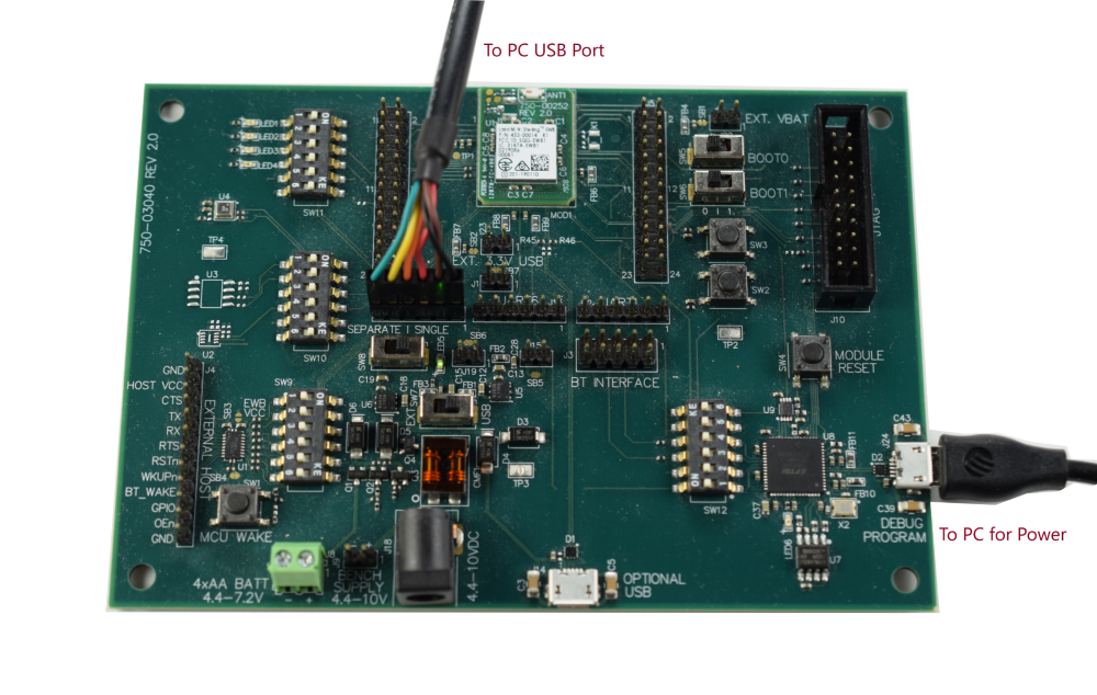
Supply power to the development board via J24. Connect the TTL-232R-3V3 cable to J7 as shown below and then connect the other end of the cable to the your Windows PC. Then use Windows Device Manager determine the COM port for the TTL-232R-3V3. For this tutorial, we will use COM30.
Steps
-
Login to your AWS IoT Service account and create a policy.
-
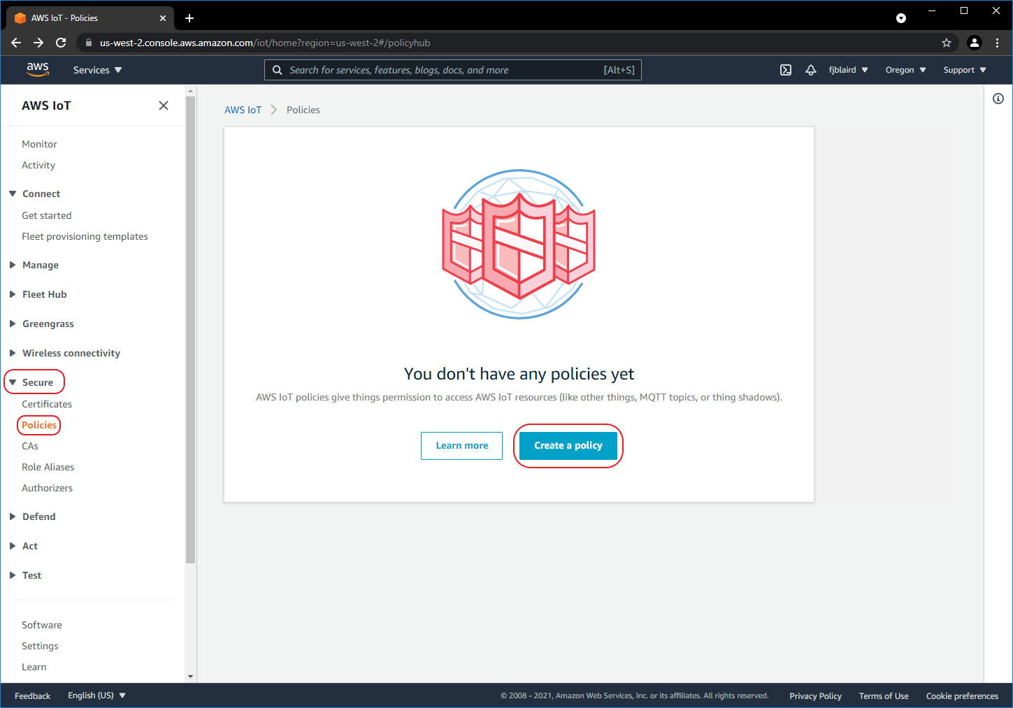
[ ] Navigate to Secure->Policies and then click Create a policy.
-
[ ] Create the policy as shown below. For Action enter iot: Connect, iot:Publish. For Resource ARN enter **. For Effect select Allow***. This policy will allow devices (e.g. Sterling EWB) to connect and publish MQTT messages.
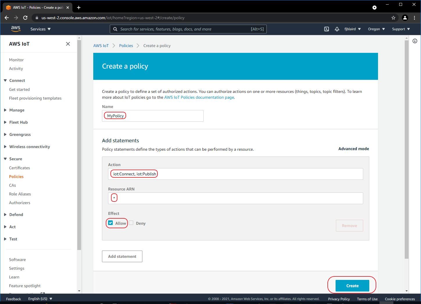
-
[ ] If the policy was created successfully, you should see the screen below.
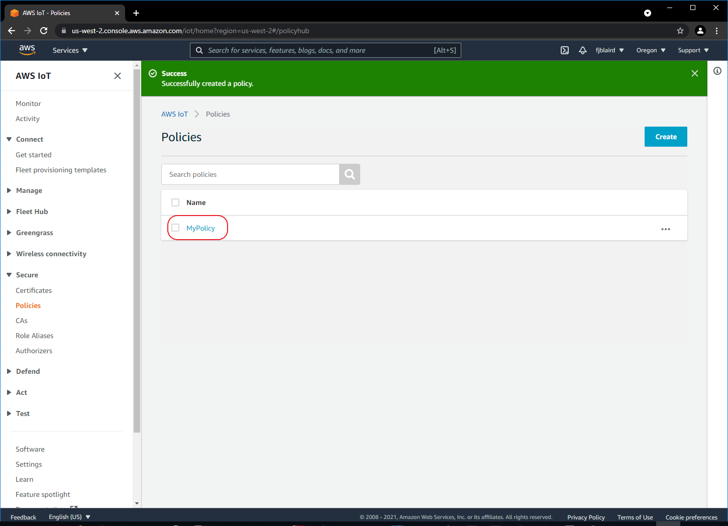
-
-
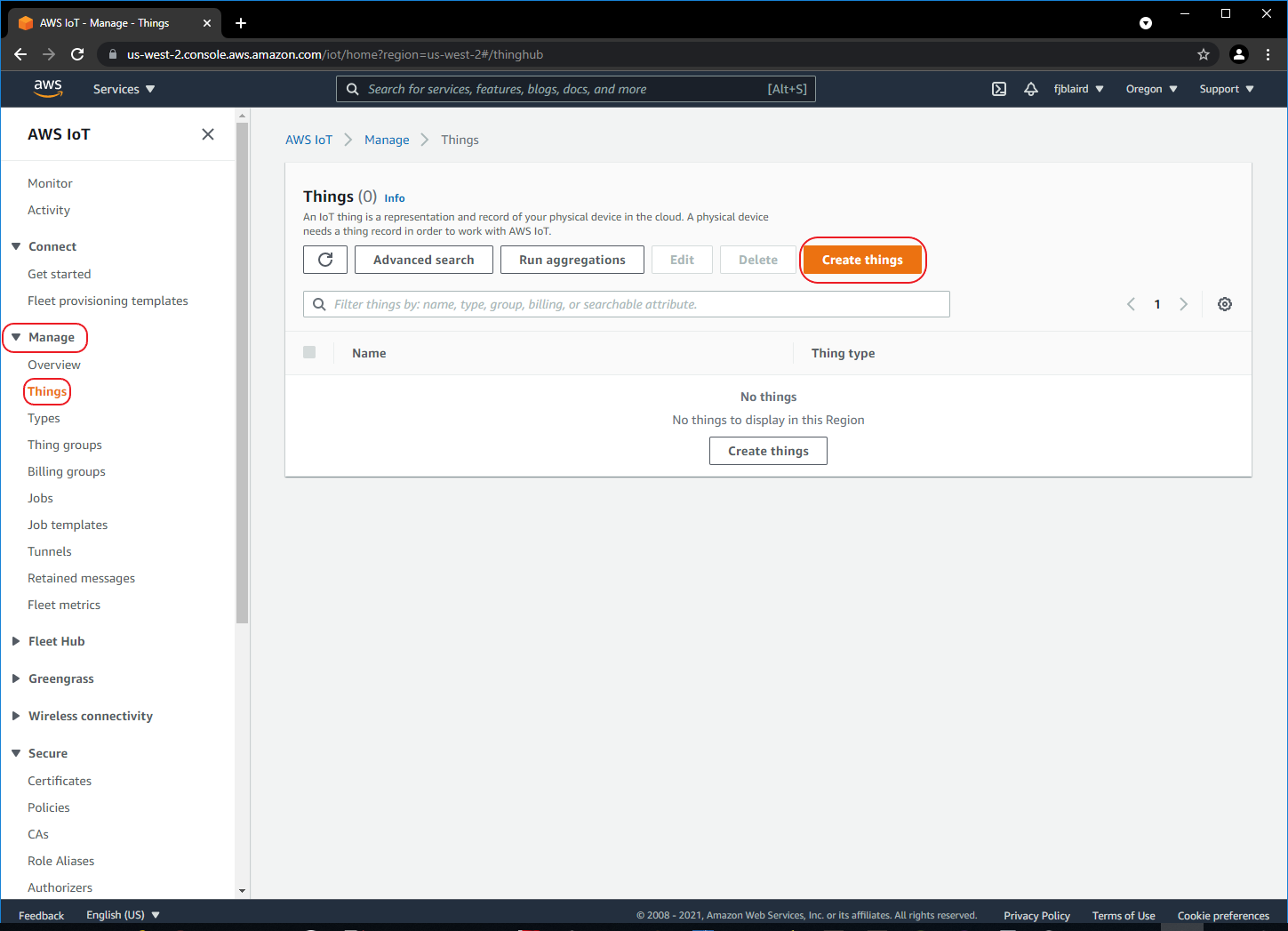
Create a Thing (i.e. Sterling EWB Sensor that will send MQTT messages).
-
[ ] Navigate to Manage->Things and then click Create things.
-
[ ] Select Create single thing and then click Next.
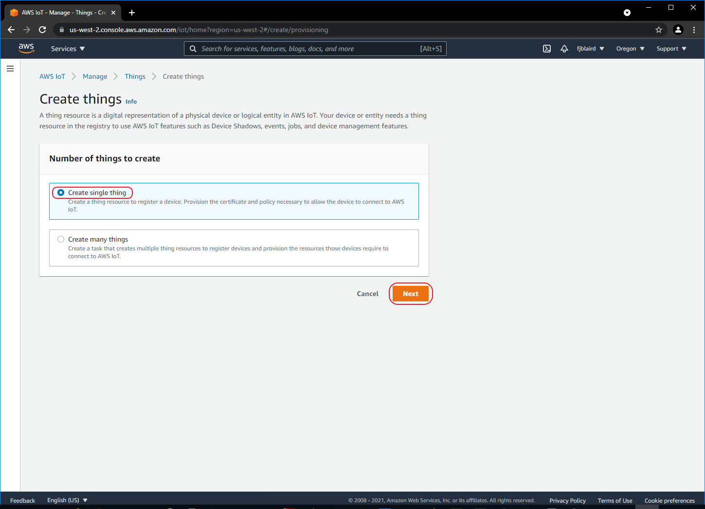
-
[ ] Name the Thing as MySensor and then click Next.
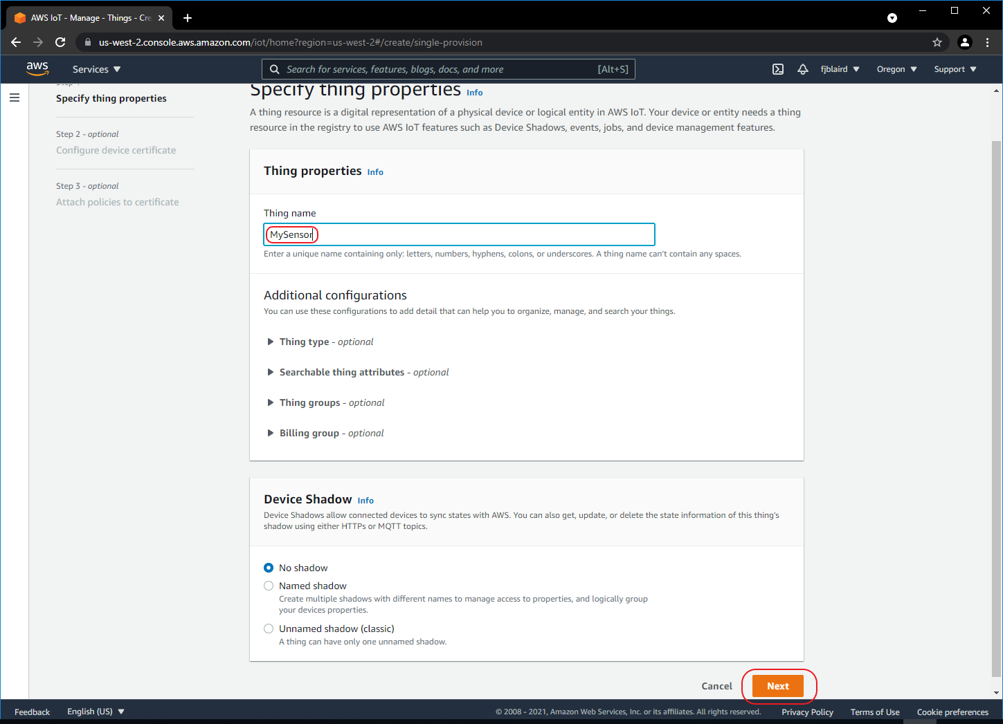
-
[ ] Select Auto-generate a certificate and then click Next.
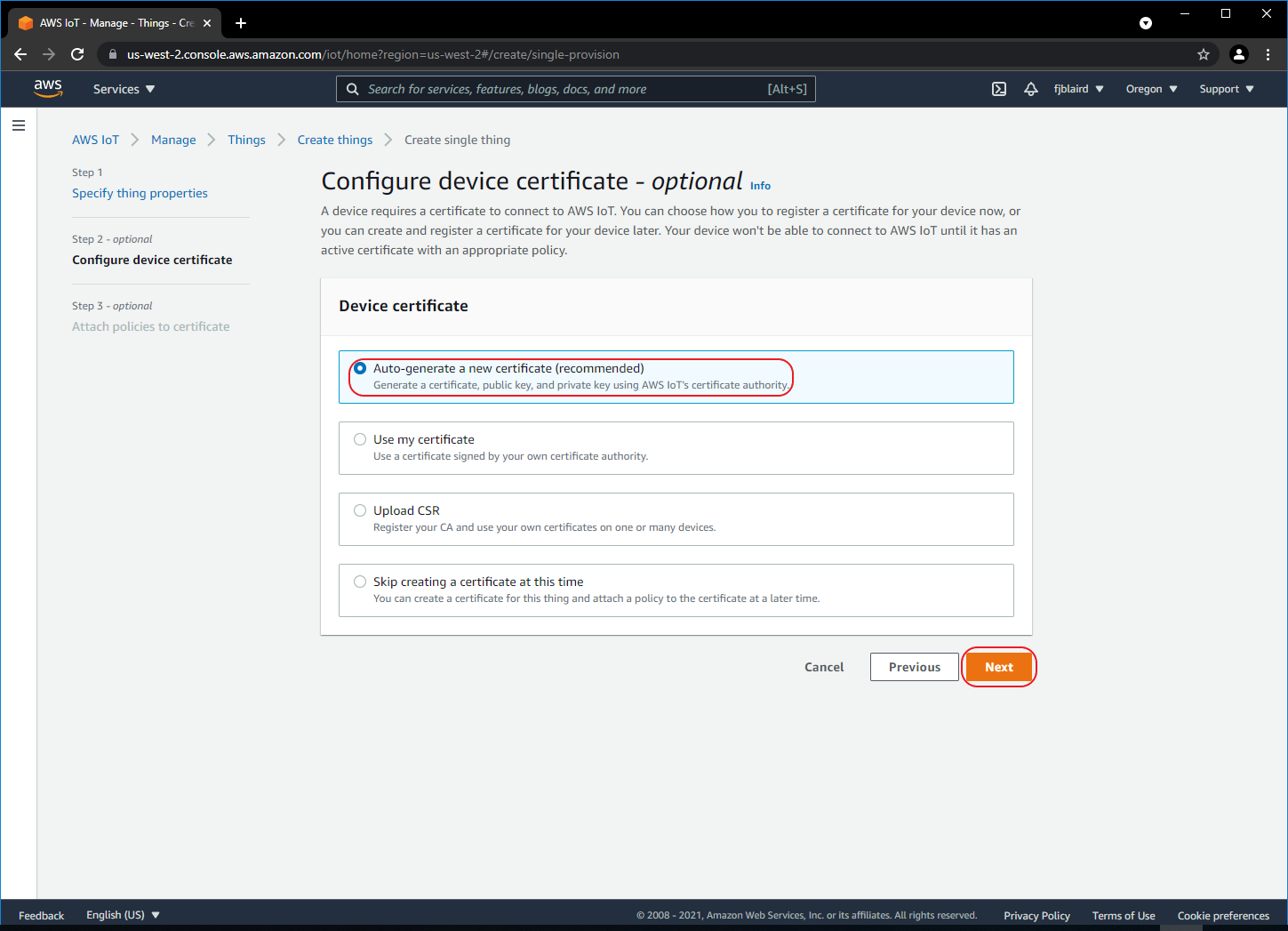
-
[ ] Attach the policy that we created to MySensor by selecting MyPolicy and then click Create thing.
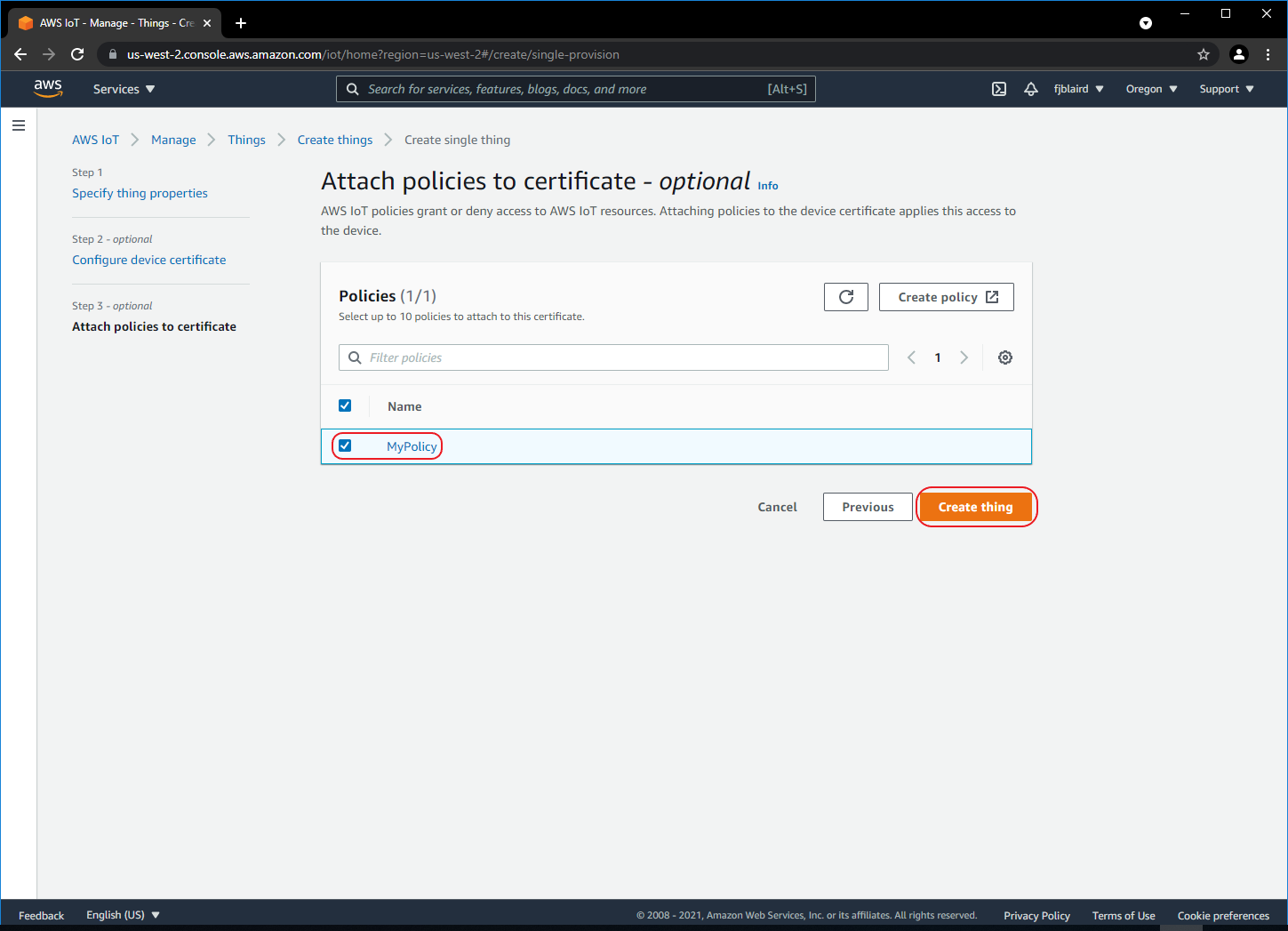
-
[ ] Download the MySensor certificate, public and private keys, and the Amazon Root CA certificates into the examples folder of the Python Samples Apps. Note, for this tutorial, we really just need the MySensor certificate and private keys, but you may download all the certificates and keys in case you need them in the future.
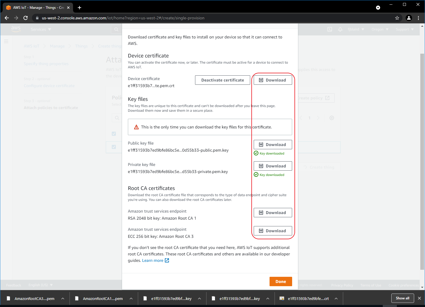
Rename the downloaded MySensor certificate as MySensor.pem.crt. Rename the public key as MySensor.public.pem.key. Rename the private key as MySensor.private.pem.key.
-
[ ] MySensor is now created as shown below. Next click MySensor.
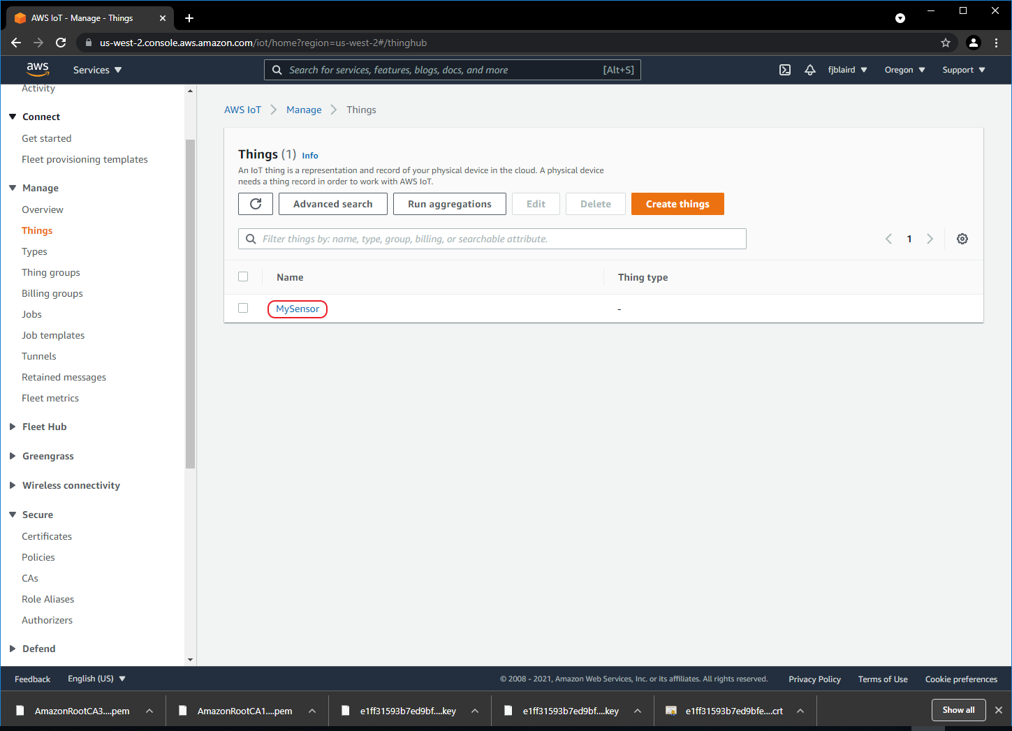
-
-
Copy and save hostname/endpoint into a textfile.
-
[ ] Select the Interact tab and then click View Settings.
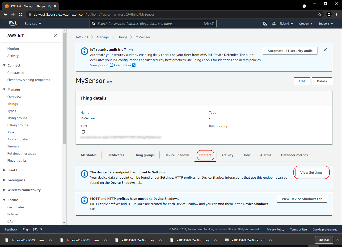
-
[ ] Copy the endpoint url and save into a textfile. We will need this later when we run our Python sample scripts. It will be used as the hostname.
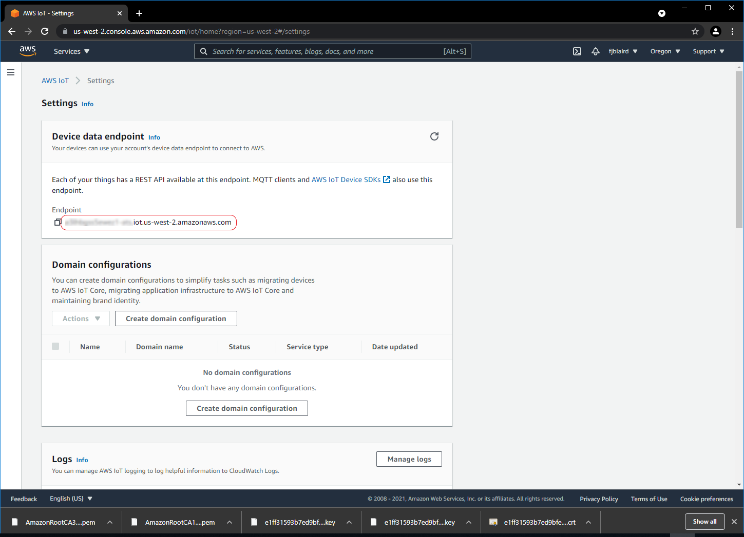
-
-
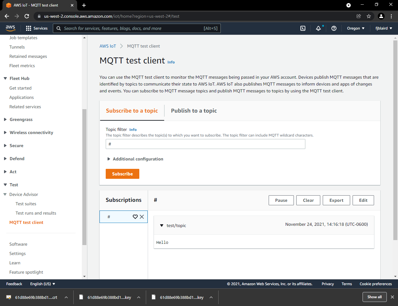
Setup the AWS MQTT Test Client.
Navigate to Test->MQTT test client. Enter # on the Topic filter. Expand Additional configuration and select Display payload as strings. Then click Subscribe. # should be added to Subscriptions.
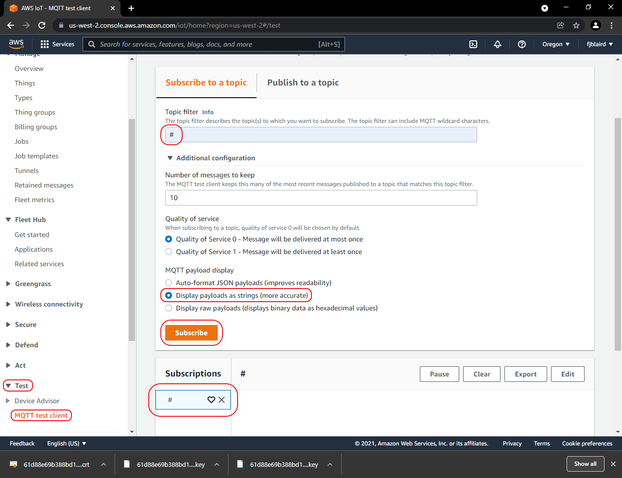
-
Send MQTT messages from the EWB.
-
[ ] Open a cmd prompt on the ATCommands_SampleApps examples folder.
-
[ ] Connect to an access point using the join.py script.
join.py -u COM30 -s NameOfYourAP -p YourPassphrase -
[ ] Load the MySensor certifcate and private key into the EWB with the client_cert.py script.
client_cert.py -u COM30 --cert MySensor.pem.crt --key MySensor.private.pem.key -
[ ] Send a message with the mqtt.py script.
mqtt.py -u COM30 -p 8883 --host TheEndPointURLYouCopiedFromStep3 --ssl NoVerifyHost --topic test/topic --body Hello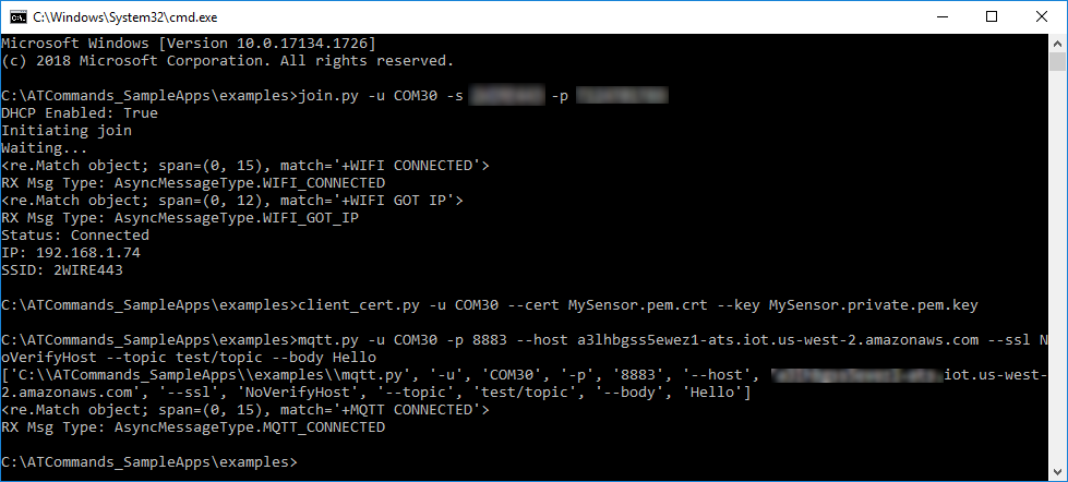
-
[ ] The hello message is received on the AWS MQTT Test Client.
-