/filters:background_color(white)/2025-01/453-00219%20front4.416.png)
Integrating FreeRTOS
The NXP development environment, MCUXpresso, includes support for FreeRTOS. Template projects selected should include FreeRTOS support.
Creating a Project in MCUXpresso
The following describes the steps required for creating an initial project within which support for the Veda SL917 can be added.
Required Hardware
Two NXP evaluation kits were investigated for Veda SL917 integration as follows.
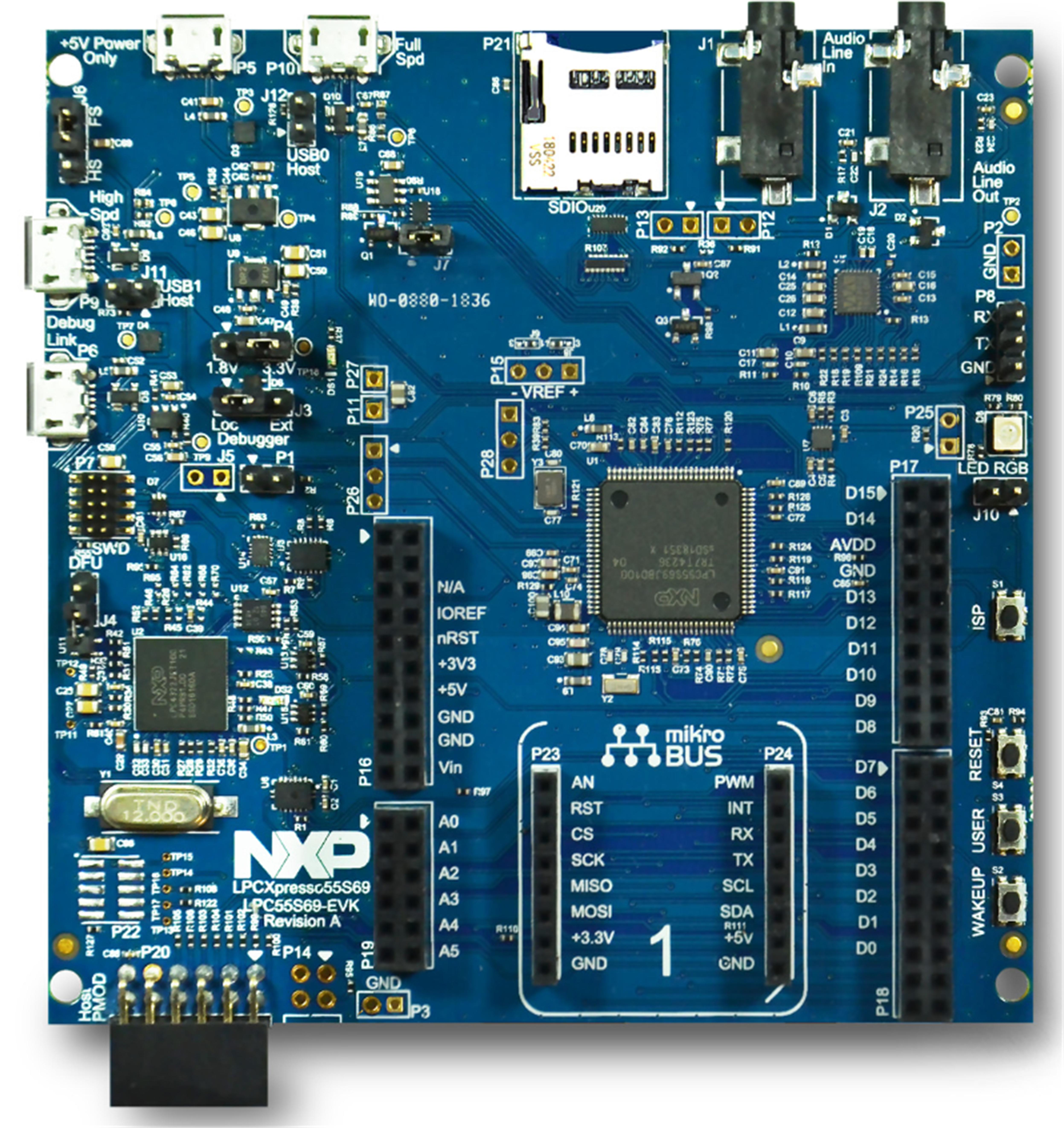
LPC55S28-EVK
The LPC55S28-EVK is based on a single M33 core LPC55S28 MCU. The evaluation kit profile is shown below.
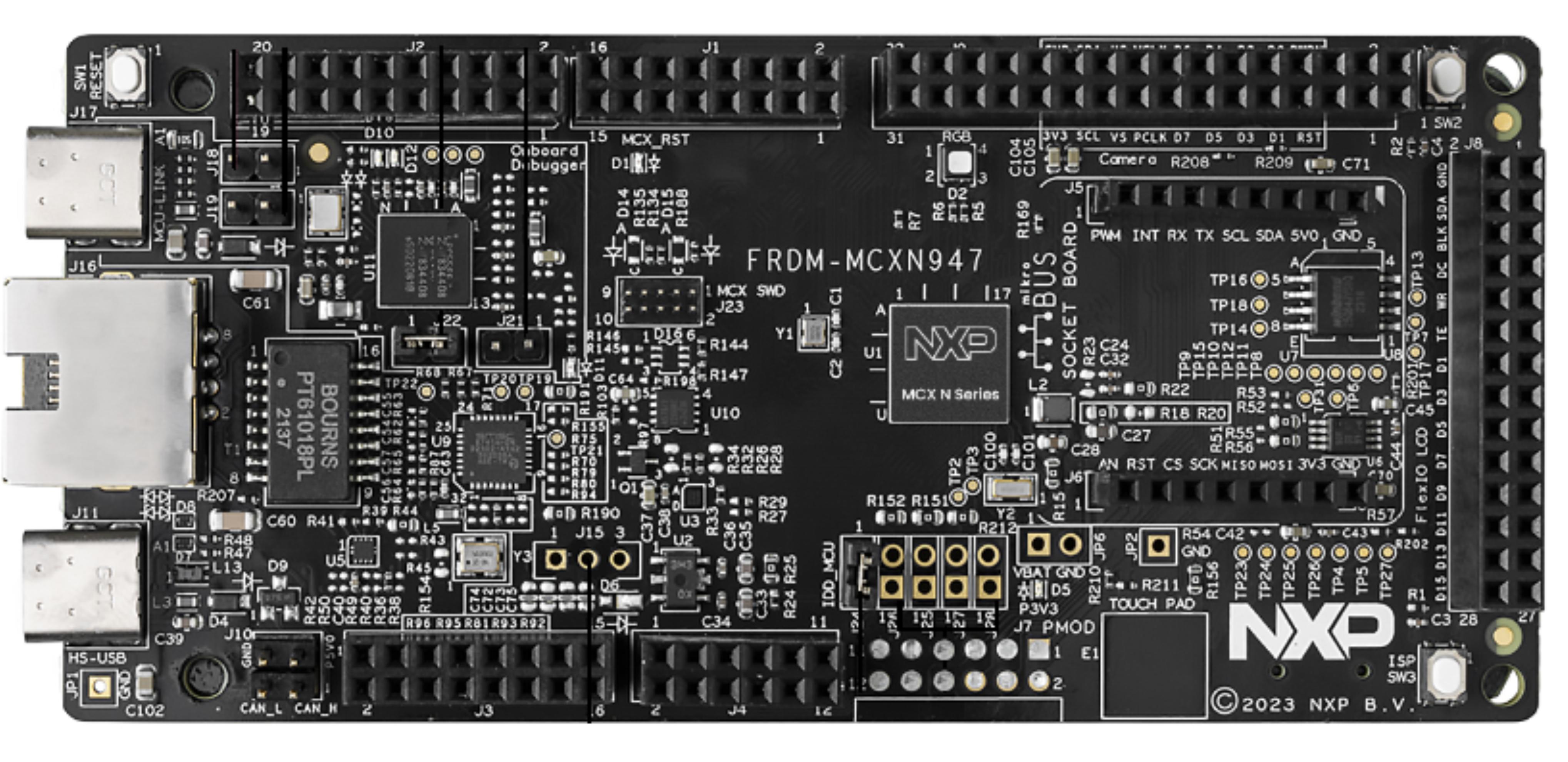
FRDM-MCXN947
The FRDM-MCXN947 Development Board is based on the MCXN947. This is a dual M33 core based MCU. The Development Board profile is shown below.
Hardware selection hints
RAM and Flash requirements depend upon the functionality required. As a minimum, 256 to 512KB of flash and 64 to 128KB of RAM are recommended. More complex applications requiring a full TCP/IP stack with Secure Connections require between 512KB to 1MB of flash and up to 256KB of RAM. High end applications will require over 1MB of flash and over 256KB of RAM.
It should be ensured that a communications interface to the Veda SL917 (either SPI or UART) is available, and sufficient GPIO for handshaking features.
The development boards selected for this investigation (LPC55S28-EVK 512KB flash, 240KB RAM, FRDM-MCXN947 1MB flash per core, 512KB RAM) were suitable for mid to high tier applications.
If a development board is being selected for evaluation, it’s also recommended to consider boards where a Mikro E port is available to simplify connection of the Veda SL917.
When selecting the board, the GPIOs used for the Mikro E port should be reviewed carefully.
In the case of the LPC55S28-EVK, it was found the RESET connection to the Veda SL917 was unavailable for direct control. This was instead coupled directly to the board Reset button.
In the case of the FRDM-MCXN947, it was found the SLEEP connection to the Veda SL917 was connected to an AD input on the host MCU. This pin can only be used as an AD input, meaning the SLEEP functionality was unavailable.
Should this functionality be required for the selected development kit, modifications will be required (e.g. tracks cut, bridging wires added).
Veda SL917 interface identification
The host MCU pins used to connect to the Veda SL917 should be identified. If using a development kit, the schematics provided (LPC55S28-EVK, FRDM-MCXN947) by NXP should be referred to.
Details of the Veda SL917 hardware interface are described in detail in the Hardware Overview.
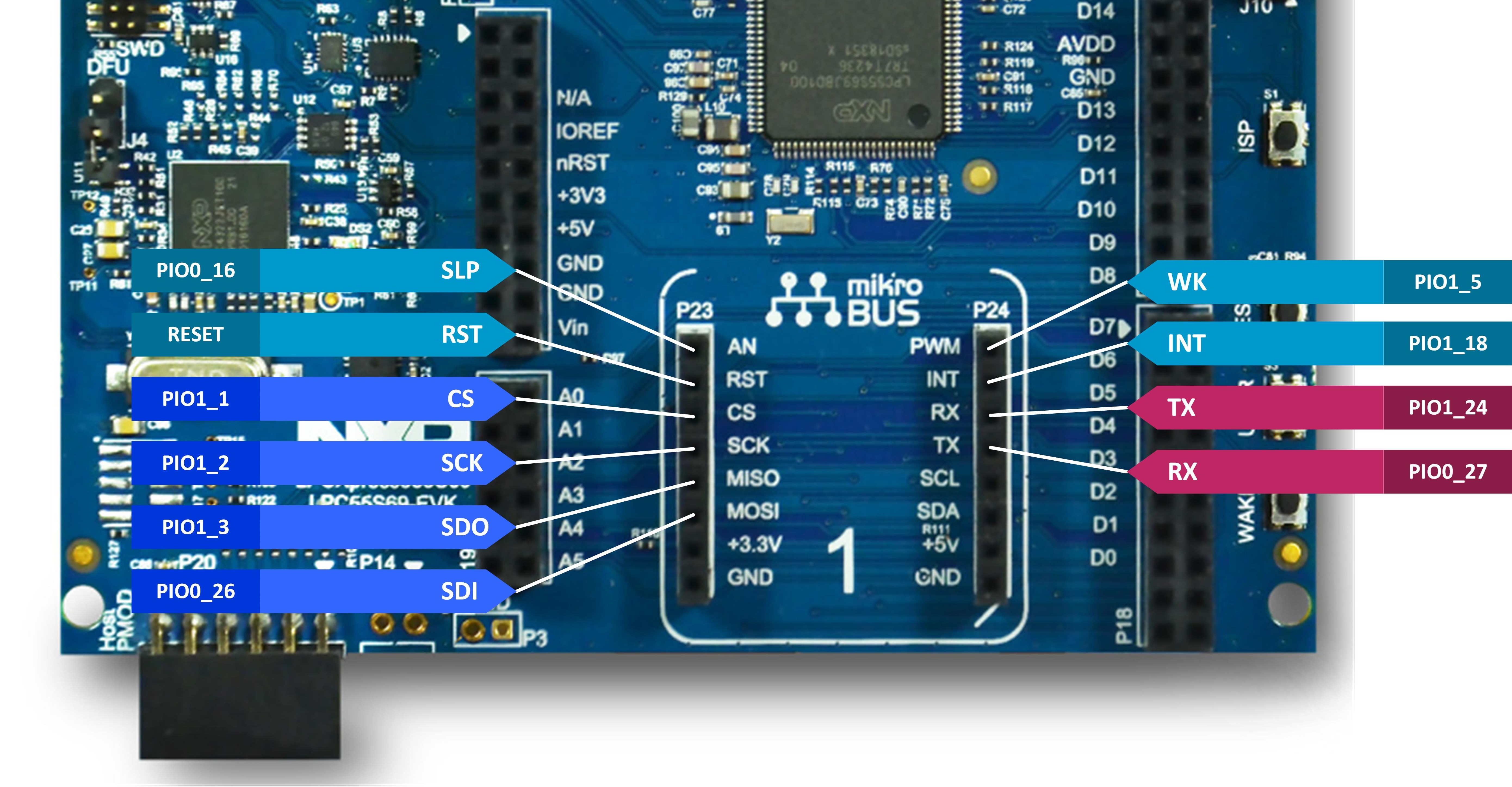
The Veda SL917 interface for the LPC55S28-EVK is shown below.
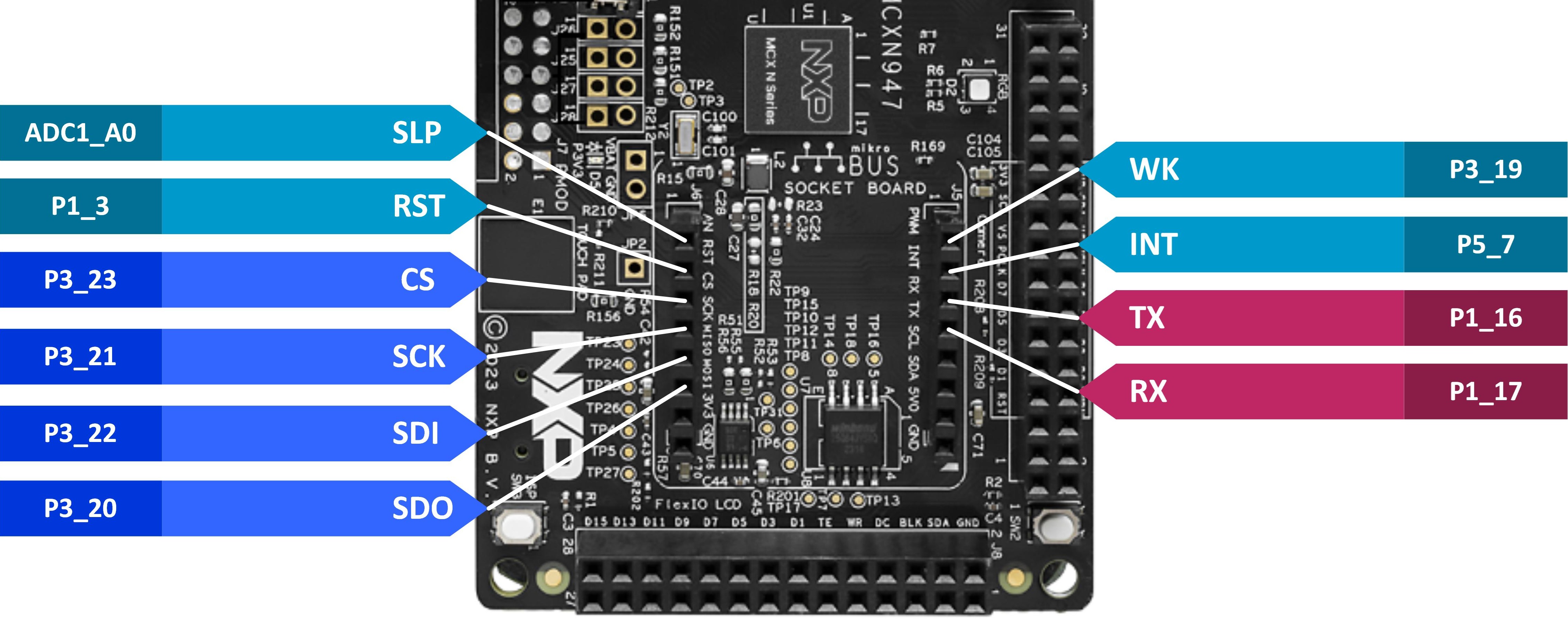
The Veda SL917 interface for the FRDM-MCXN947 is shown below.
Adding support for an NXP MCU Family to MCUXpresso
Support for MCUs and associated development boards is added to MCUXpresso as discrete SDKs. The SDK for the MCU or development board must first be added before an application can be created.
From within MCUXpresso, the SDK Management button should be clicked, as highlighted below.
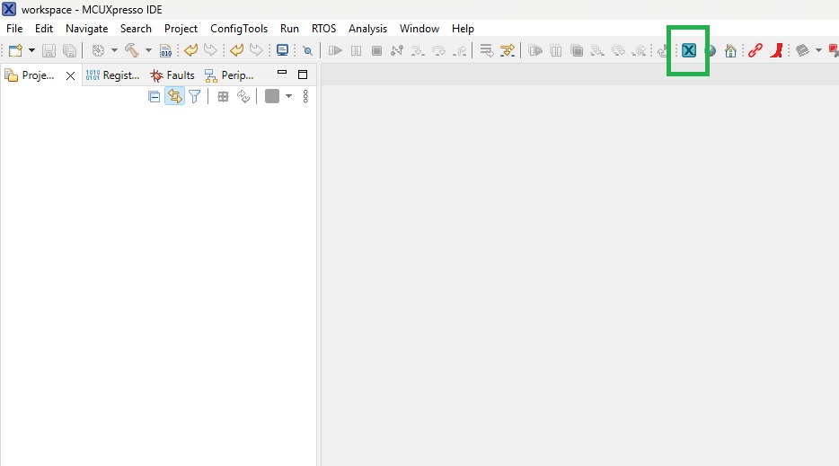
This opens the SDK Management dialog, as shown below.
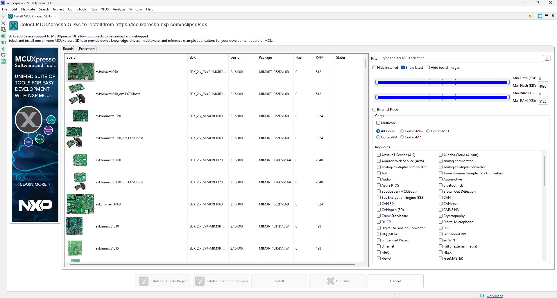
If adding support for an MCU, click the ‘Processors’ tab. Support is added for development boards via the ‘Boards’ tab.
Locate the required SDK using the scrollbar to the right of the list of boards or processors.
The following shows the LPC55S28-EVK board being selected.
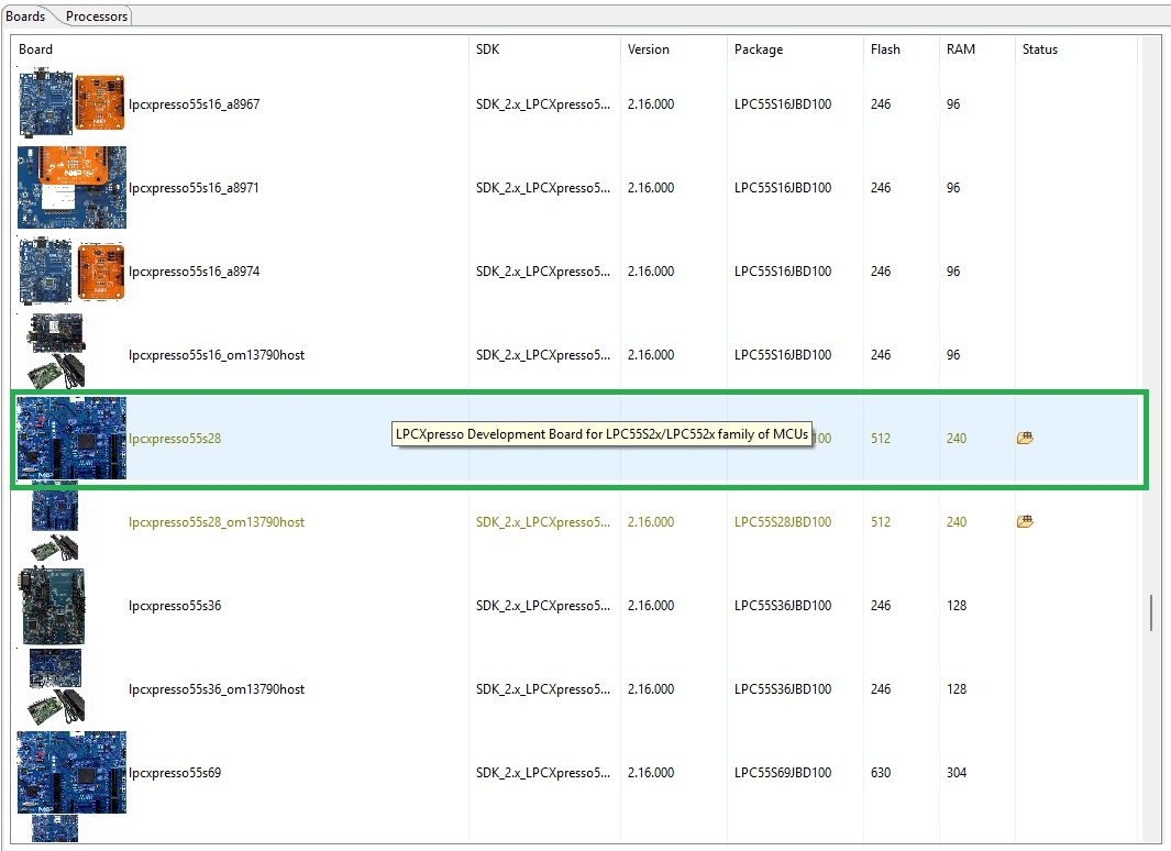
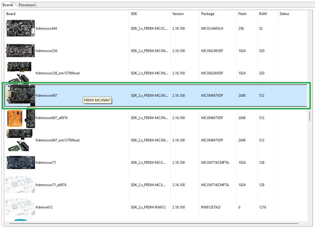
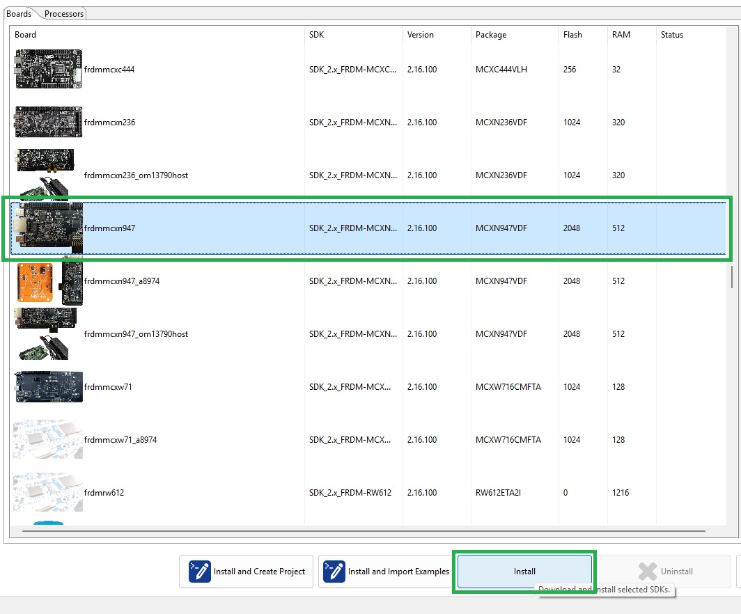
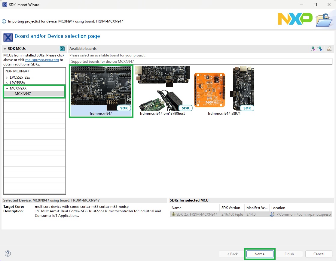
The following shows the FRDM-MCXN947 board being selected.
Having selected a board or processor, click Install as shown below.
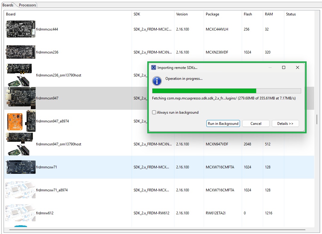
Installation of the board or processor SDK begins. Details of installation progress appear as shown below.
Creating a new “Starter Project”
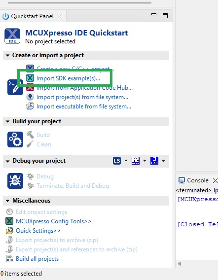
SDK Example Projects are created via the Quickstart Panel option Import SDK example(s) . . . as shown below.
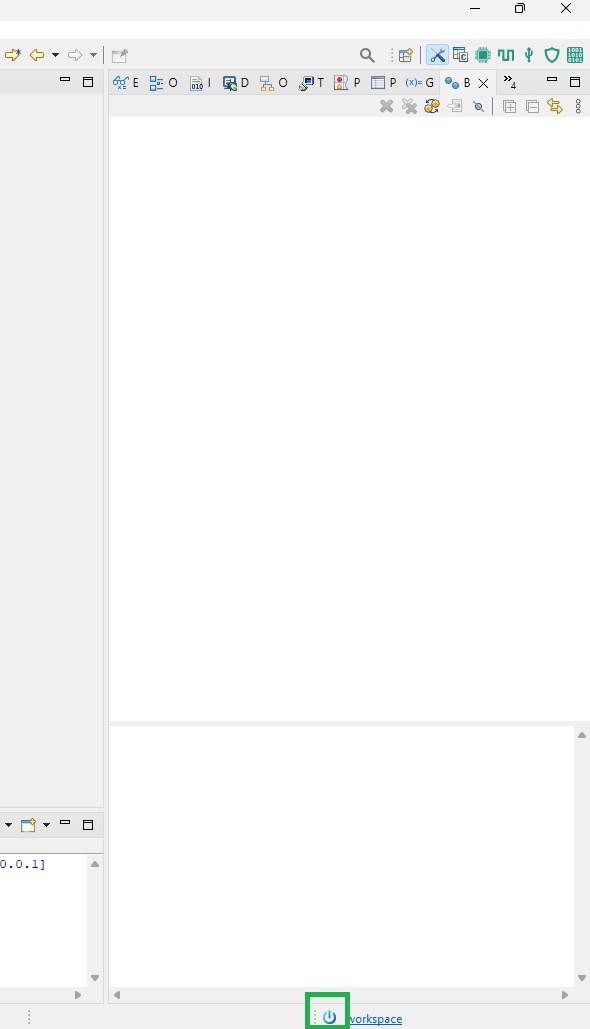
If the Quickstart Panel is not visible, it can be opened via the Quickstart button at the foot of the environment window as highlighted below.
After clicking Import SDK example(s) . . . a list of available SDKs is displayed as shown below.
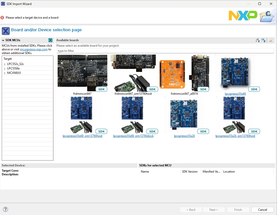
The pane to the left lists available targets for the SDK example. Select the board or processor intended to run the SDK example and click Next as shown below.
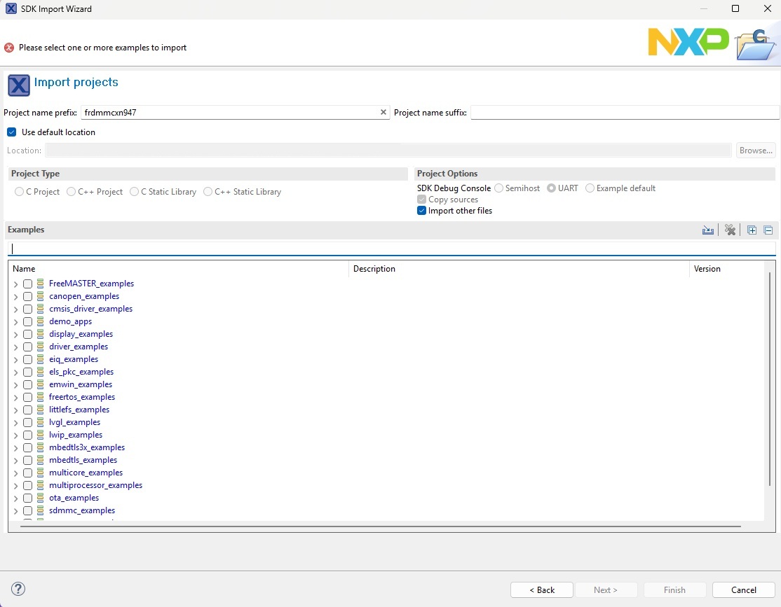
A list of available examples is then displayed as shown below.
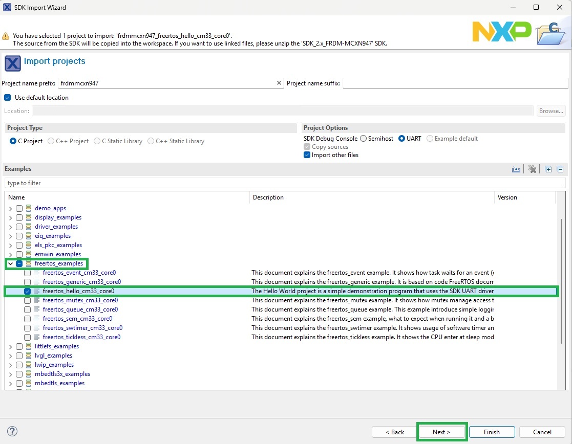
A range of FreeRTOS enabled example applications are available. For this investigation, we’ll use the ‘freertos_hello’ example. This includes debug UART support to allow print statement output via the development board virtual UART.
Having selected the example application, click Next as shown below.
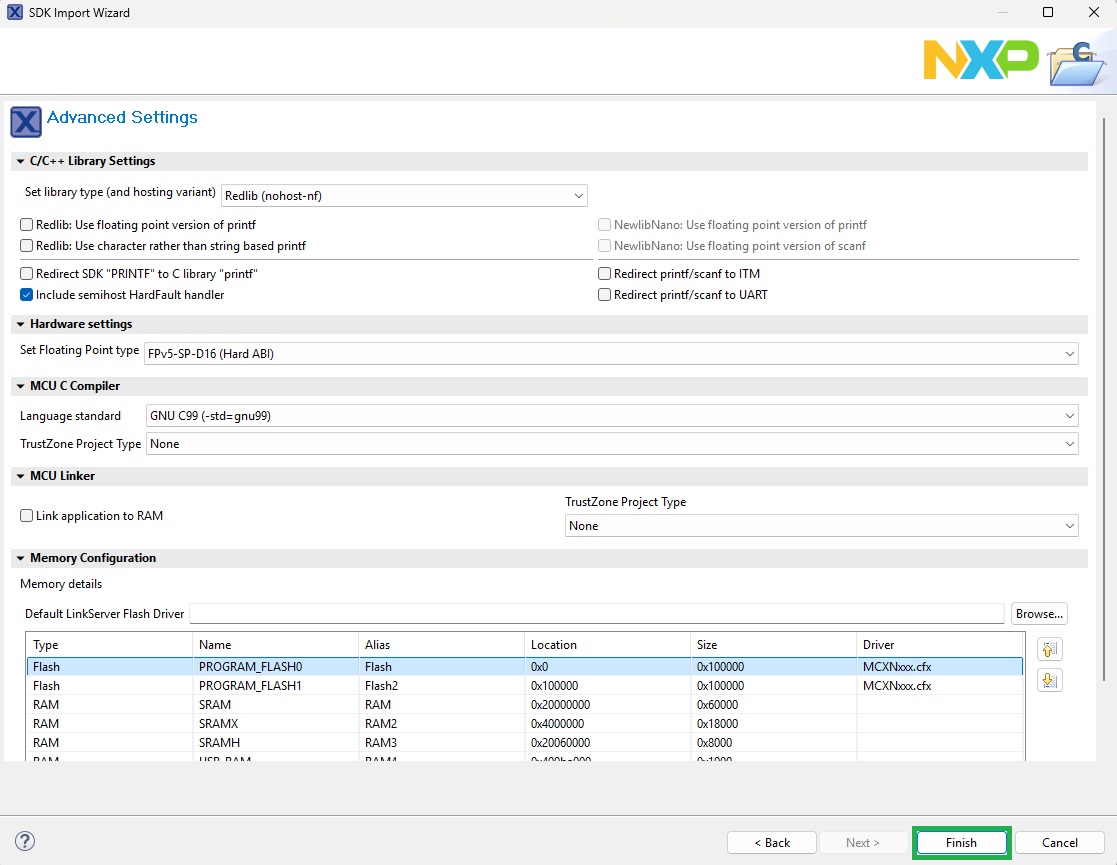
A summary of flash and RAM usage displays. This can be left at default values, then click Finish as shown below.
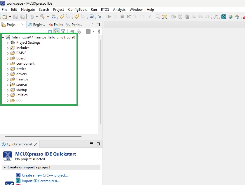
The example application files are then copied to the Workspace with the finalised stucture appearing as shown below.
Testing the Starter Project
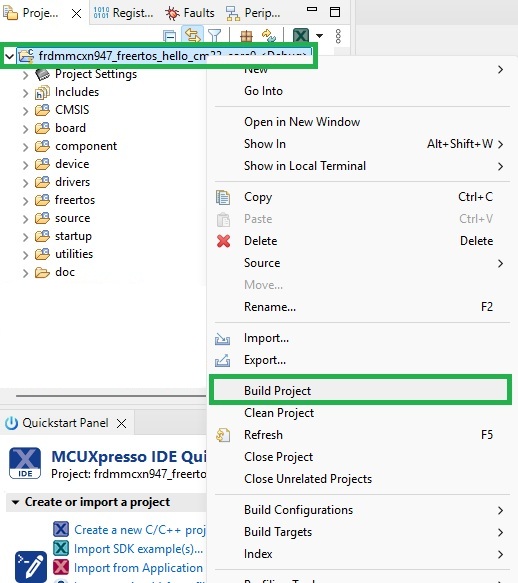
Build the example application by right clicking the project name, then selecting Build Project from the context menu as shown below.
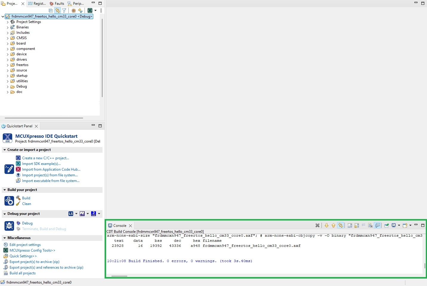
Following completion of the build process, a summary displays in the pane at the foot of the environment as shown below.
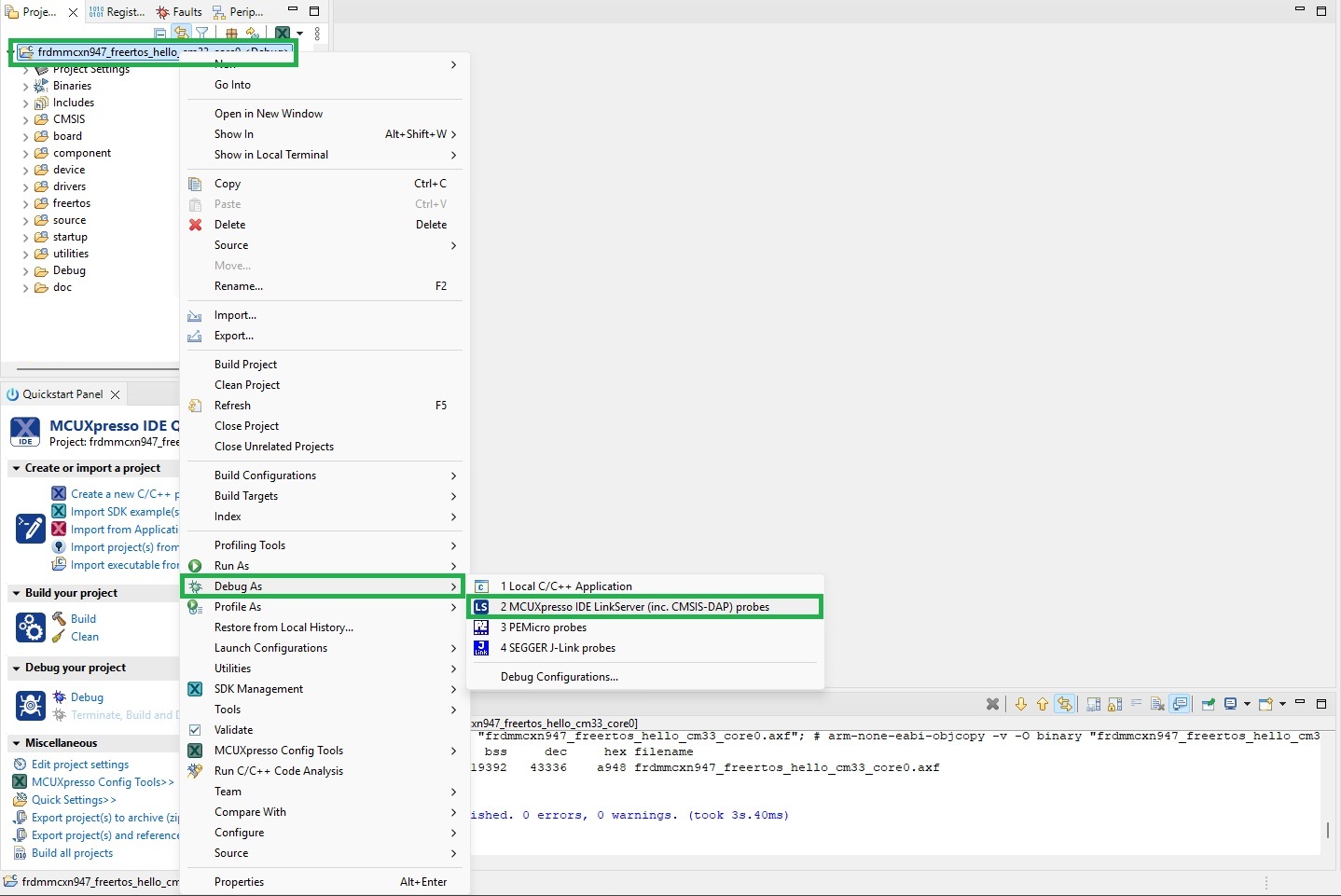
The application can then be programmed to the board or processor for a debug session to be started. Right click the project name, then click the Debug As option in the context menu. When a development board is being used, select the MCUXpresso IDE LinkServer (inc. CMSIS-DAP) probes option as shown below.
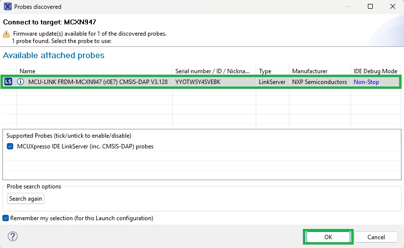
A list of available targets is then displayed. Select the intended target and click OK as shown below.
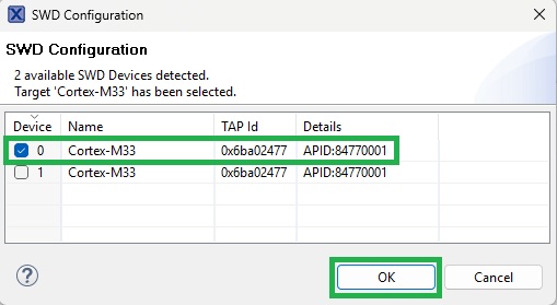
If a multi-core part is in use, the Core Selection dialog is displayed. Select the core intended for debug and click OK as shown below.
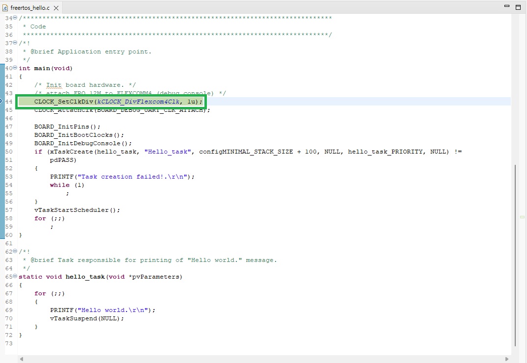
The debug session then starts. Execution is suspended on the first line of example application code as shown below.
Step into code using the Step Into button as shown below.
Step over statements using the Step Over button as shown below.
Run the application using the Run button as shown below.
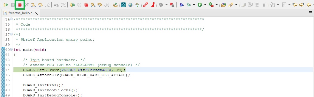
Terminate the debug session using the Stop button as shown below.
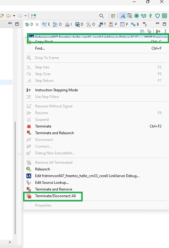
If the board or processor is reset externally, connectivity with the debug session will be lost. In event of this occuring, the debug session is terminated using the ‘Terminate/Disconnect All’ option. This is located by right clicking the project name in the Debug pane as shown below.
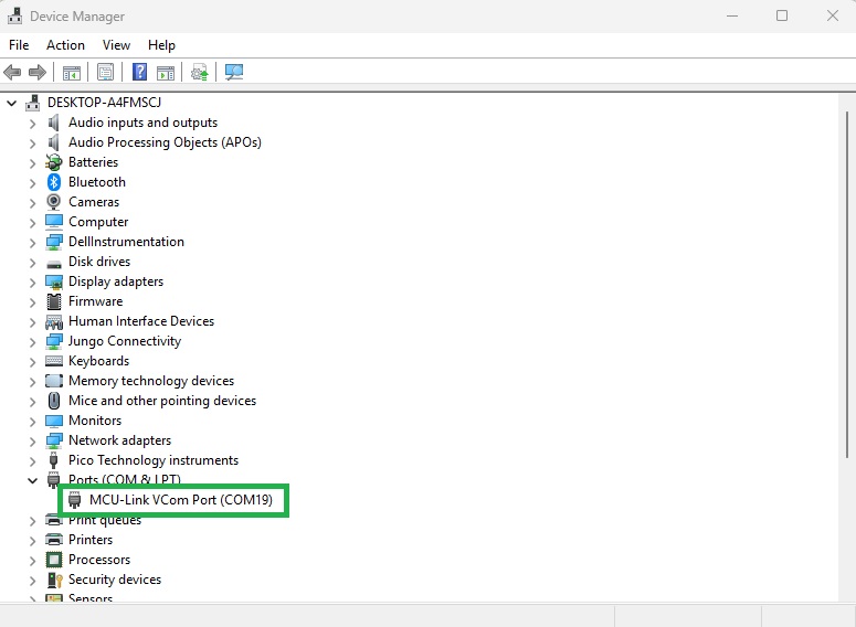
The FreeRTOS Hello application spawns a single thread and outputs the text ‘Hello World’ from the thread before suspending it. To ensure the application is performing this step, identify the COM port associated with the board as shown below.
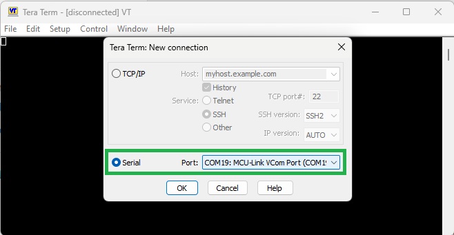
Use a serial monitoring application to inspect the output of the application. Teraterm was used in this instance.
Start the serial monitoring application with the serial port settings configured as 115200, 8, n, 1 with no flow control.
For Teraterm, the ‘New connection’ dialog is displayed upon opening the application. Select the serial port as shown below.
Select the Serial port . . . item from the Setup menu as shown below.
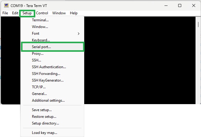
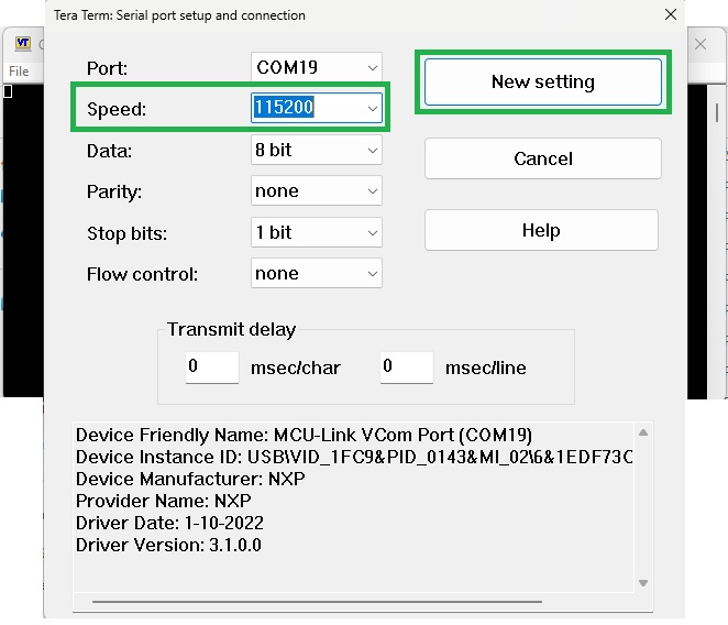
Configure serial port settings and the click New setting as shown below.
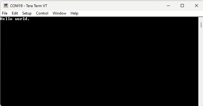
Running the example application will result in the following output being displayed as shown below.
Adding support for Veda SL917
The following describes the steps neccessary for adding support for the Veda SL917 to the example application.
Clone the WiseConnect SDK
The WiseConnect SDK is provided by Silabs. It provides all libraries needed for harnessing the WiFi and BLE features of the Veda SL917. Git clone the WiseConnect SDK to the Workspace folder at the same level as the example application. This will allow the WiseConnect SDK code to be shared across all of the projects in the Workspace and avoid multiple copies being in use.
Clone the Simplicity SDK
The Simplicity SDK is also provided by Silabs. It implements foundational features and types used by the WiseConnect SDK. Git clone it at the same folder level as the WiseConnect SDK.
Resource Filtering
Files from the WiseConnect SDK and Simplicity SDK are added as linked resources within MCUXpresso. Linked resources are not copied into the project, but are accessed from elsewhere within the filesystem via symbolic links. This allows the same file to be reused across multiple projects. Because the WiseConnect SDK and Simplicity SDK folders will be added to the example project unchanged, resource filtering must be used to ensure only the required folders and files are used within the application. This approach avoids the need to remove any folders or files from the cloned resources.
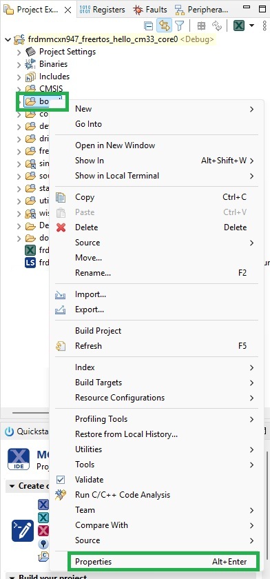
To apply a resource filter, open the project Properties dialog by right clicking on the folder within the project where the resource filter is to be applied and selecting Properties as shown below.
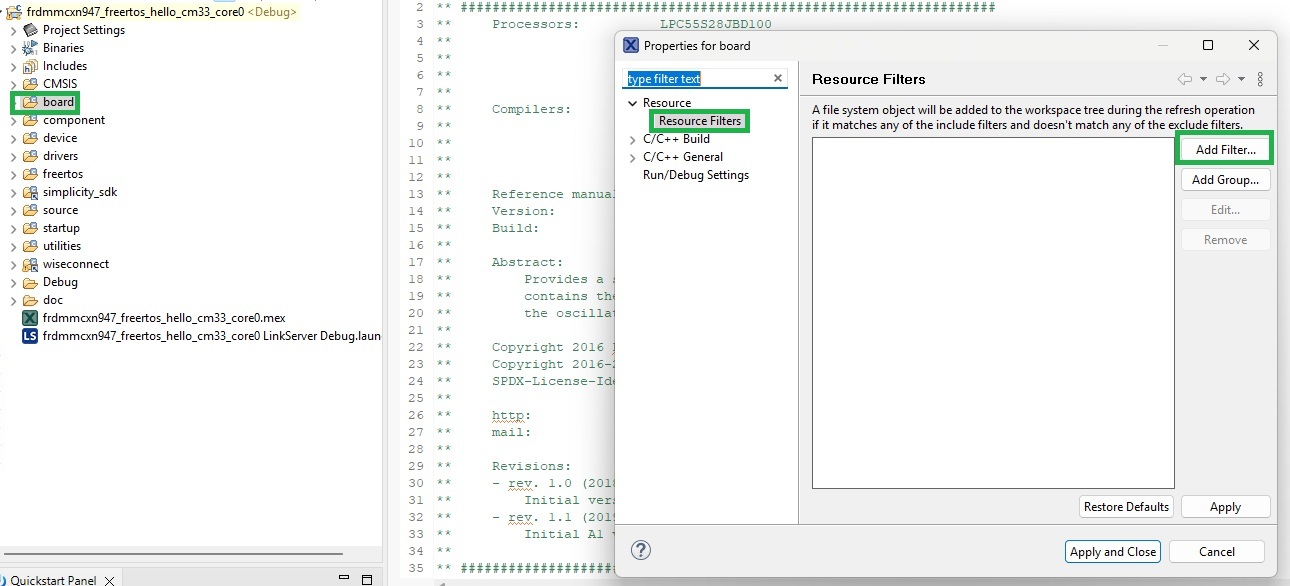
The Properties dialog for the selected project folder displays. Add resource Filters by selecting Resource Filters item under 'Resource’ in the tree view to the left of the dialog. Click Add Filter . . . to add a resource filter, as shown below.
The ‘Add Resource Filter’ dialog displays as shown below.
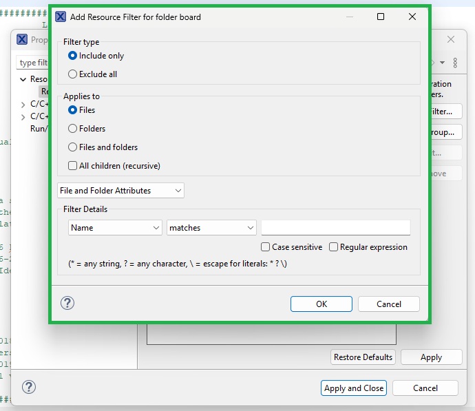
Filter types can be either Include only, where referenced files or folders are added to the project, or Exclude all, where the referenced files or folders are excluded from the build. If a single folder needed to be excluded for example, set the ‘Applies to’ to Folders, the ‘Filter type’ set to Exclude all and the folder name entered in the text box within the ‘Filter Details’ group. Once details of the resource filter have been added, click OK to store them.
In the Properties dialog, click Apply to apply the filter to the project.
Adding the Simplicity SDK to the project as a linked resource
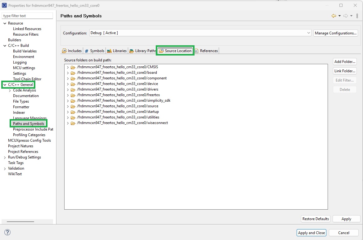
Add the required files from the Simplicity SDK to the project. Right click the project name, then select the Properties option. From the tree view on the left, select Paths and Symbols form the ‘C/C++ General’ group. Open the ‘Source Location’ pane as shown below.
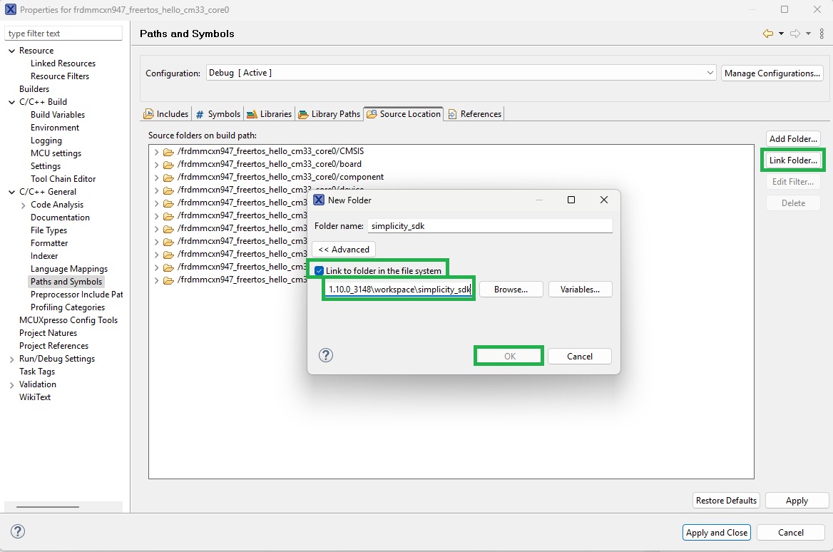
Click the Link Folder button. In the dialog, select the Link to folder in the file system checkbox and navigate to the top level Simplicity SDK folder. Once located, click OK as shown below.
Filtering unused Simplicity SDK files
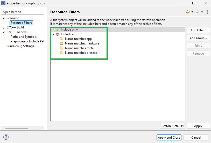
Only the folders ‘platform’ and ‘util’ in the Simplicity SDK folder structure are required. A resource filter can be set up to either include only these folders, or to exclude the other folders in the folder structure. The resource filter below excludes unused folders.
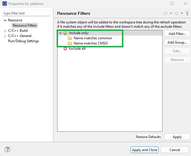
In the ‘platform’ folder, only the ‘CMSIS’ and ‘common’ folders are required. An include filter is added here as shown below.
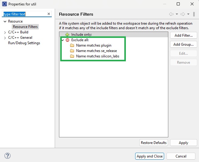
In the ‘util’ folder, only the ‘third_party’ folder is required. The filter shown below excludes the other folders from the project.
In the ‘platform/CMSIS’ folder, only the ‘RTOS2/Include’ folder is required. In the ‘platform/common’ folder, only the ‘inc’ and ‘src’ folders are required.
In the ‘util/third_party’ folder, only the ‘freertos/cmsis’ folder is required.
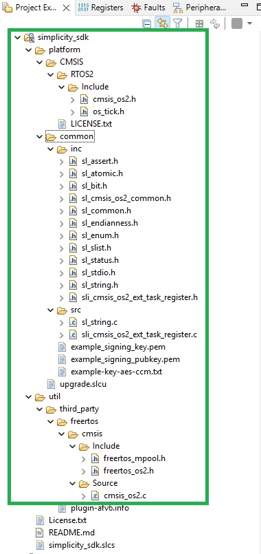
Further filtering of source and header files is then needed. The ultimate required set of files is shown below.
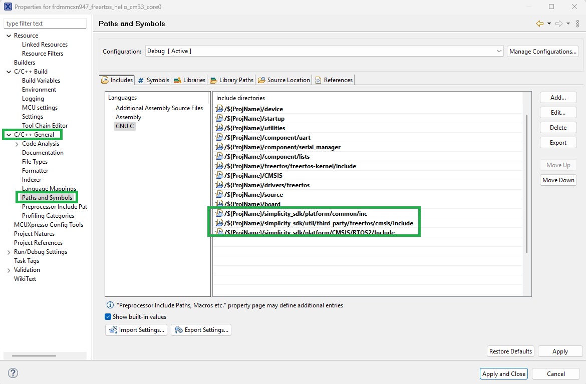
Adding Simplicity SDK include paths
Add the Include paths for Simplicity SDK files to the project. Open the project Properties dialog should be opened, then click Paths and Symbols under the ‘C/C++ General’ item in the tree view. Add the include paths as shown below.
Adding Simplicity SDK symbols
Add Build symbols using the Paths and Symbols dialog in the project Properties dialog as shown below.
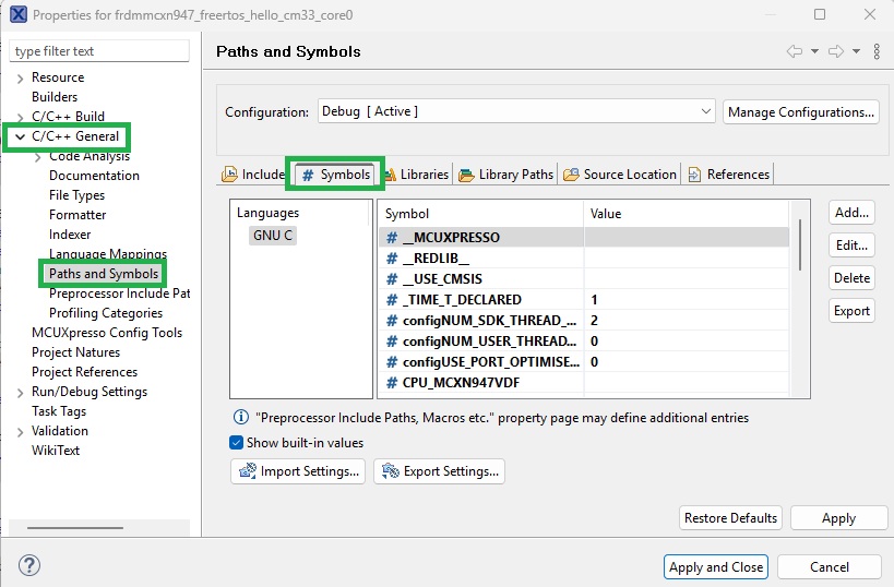
Add new symbols by clicking the Add button. This results in the dialog shown below being displayed.
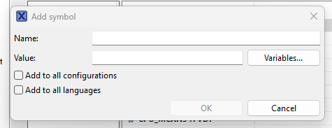
It is recommended to clicking the Add to all configurations and Add to all languages checkboxes so added symbols are available globally across the workspace.
The following symbols and values should be added.
SL_CATALOG_FREERTOS_KERNEL_PRESENT           1
configNUM_SDK_THREAD_LOCAL_STORAGE_POINTERS  2
configNUM_USER_THREAD_LOCAL_STORAGE_POINTERS 0
INCLUDE_xSemaphoreGetMutexHolder             1
INCLUDE_xQueueGetMutexHolder                 1
configUSE_PORT_OPTIMISED_TASK_SELECTION      0
Changes required to FreeRTOSConfig.h
The FreeRTOSConfig.h file is used to set FreeRTOS configuration items. It resides in the top level ‘source’ folder of the example application. This file must be modified manually to include configuration items and paths used by the Simplicity SDK files and later the WiseConnect SDK files.
Note that this file is autogenerated by MCUXpresso and changes made to it are overwritten during later code generation steps. Use the autogenerated .bak file to track the following manually added changes.
At the top of the file, add an include statementto the host MCU core header file. This resides in the device folder at the root of the project folder structure.
For the FRDM-MCXN947 board, this appears as shown below.
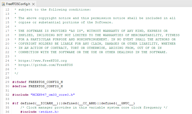
This is used later to allow the core functionality to be accessed by FreeRTOS functions.
The configuration items as follows should have their values set as shown below.
INCLUDE_eTaskGetState  1
configMAX_PRIORITIES   56
The SysTick_Handler define should be updated as follows.
#define SysTick_Handler xPortSysTickHandlerThis maps the FreeRTOS tick handler to that defined by the project.
Note in the example application the priority of the initial thread is configured as shown below.
#define hello_task_PRIORITY (configMAX_PRIORITIES - 1)This will interfere with real time behavior when other threads are added by the WiseConnect SDK. The priority should be reduced as shown below.
#define hello_task_PRIORITY (osPriorityNormal)Building and testing
The example application should now build successfully without warnings and the ‘Hello world’ output visible on the serial monitor application.
Adding WiseConnect SDK to the project as a Linked Resource
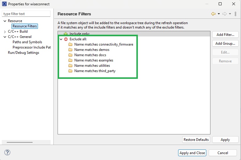
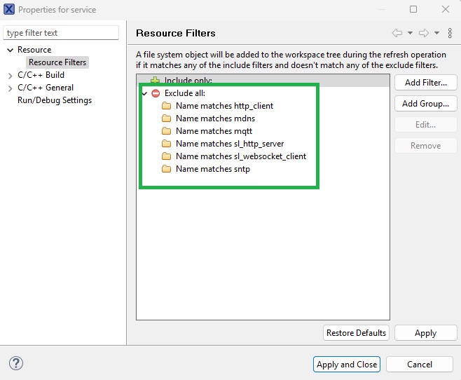
The WiseConnect SDK can now be added as a Linked Resource to the project, as per the Simplicity SDK. For an initial integration, only the top level ‘components’ and ‘resources’ folders are needed. Remaining top level folders are excluded via a Resource Filter as shown below.
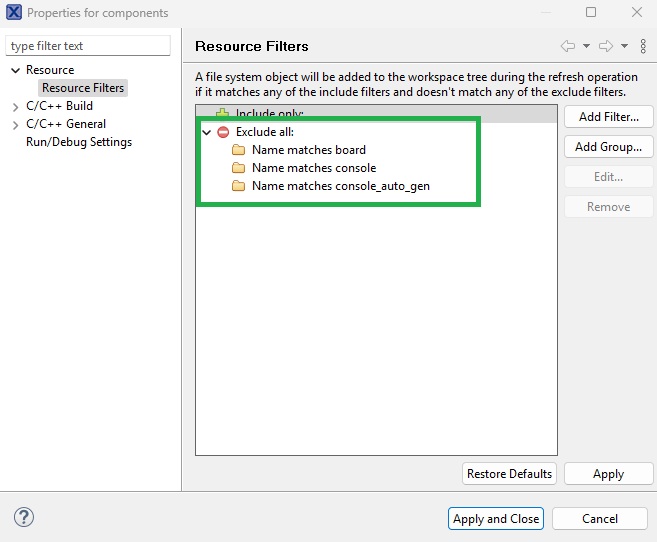
In the ‘components’ folder, the ‘board’, ‘console’ and ‘console_auto_gen’ folders are excluded as shown below.
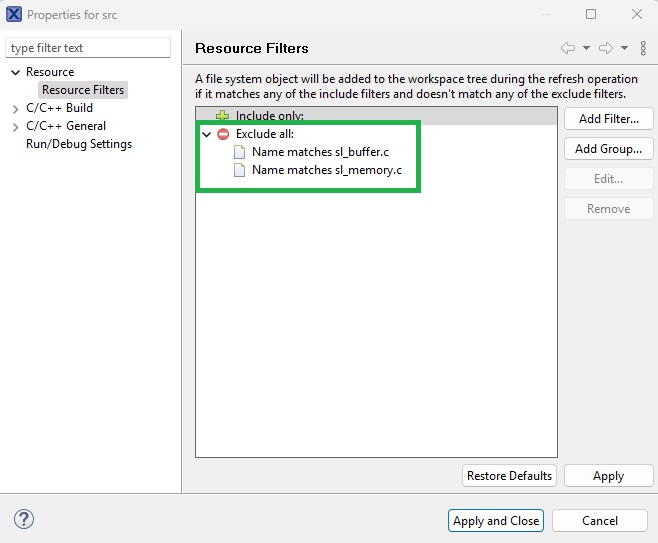
In ‘components/common/src’, the sl_buffer.c and sl_memory.c files should be excluded as shown below.
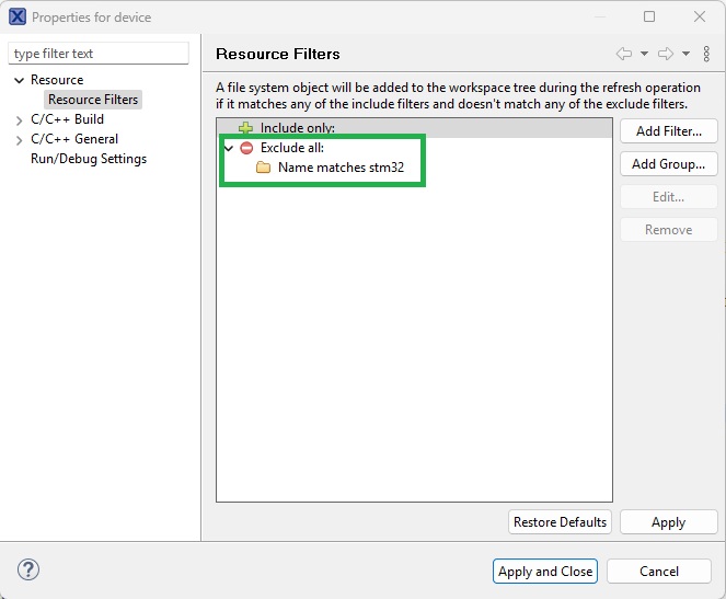
In the ‘device’ folder, only the ‘silabs’ folder is required. The ‘stm32’ folder is excluded as shown below.
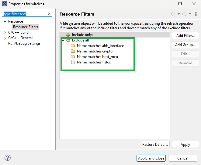
In the ‘components/device/silabs/si91x/wireless’ folder, the folders shown below are excluded.
The ‘host_mcu’ folder contains example abstraction layers for EFR32G25, EFX32, SI91X and STM32 MCUs. Any of these files should be copied to the ‘source’ folder at the root level of the example application and renamed ‘x_ncp_host.c’ where x is the name of the target host MCU (e.g. lpc55s28_ncp_host.c, mcxn947_ncp_host.c). Changes will be made to this file later to integrate it with the host MCU.
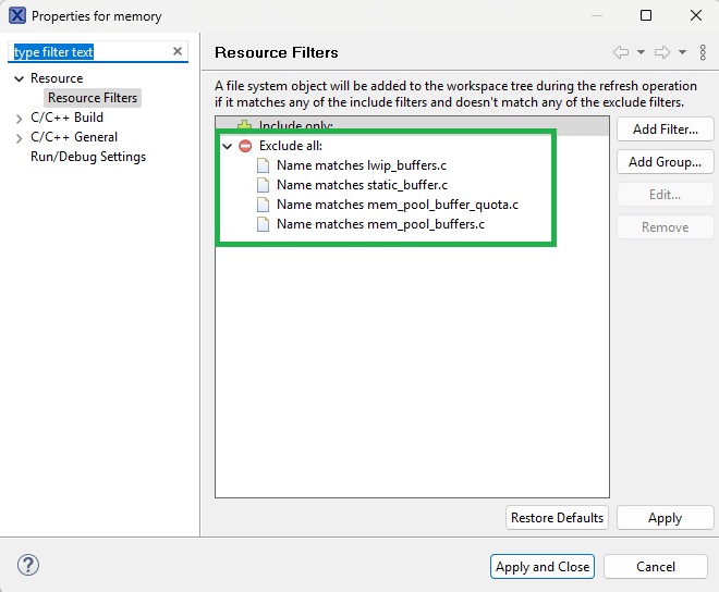
Under ‘components/device/silabs/si91x/wireless/memory’, the files shown below are excluded.
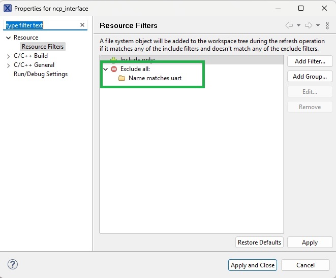
Under ‘components/device/silabs/si91x/wireless/ncp_interface’ there are two folders ‘spi’ and ‘uart’. Only the folder for the supported Veda SL917 interface should be included here and the other excluded. Failing to exclude one of the folders will result in build errors due to duplicate function names.
The following shows the ‘uart’ folder being excluded for a Veda SL917 integration using an SPI interface.
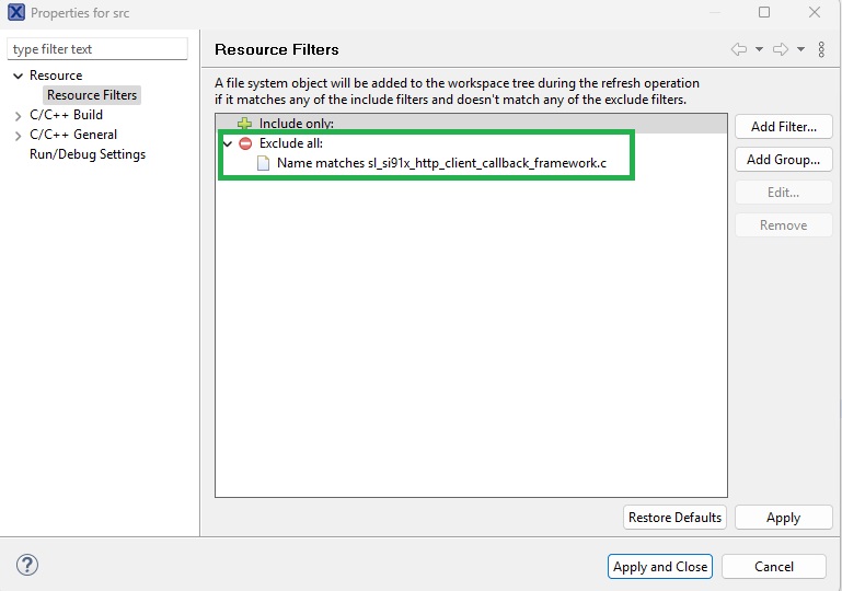
From the ‘components/device/silabs/si91x/wireless/src’ folder, the ‘sl_si91x_http_client_callback_framework.c’ file should be excluded as shown below.
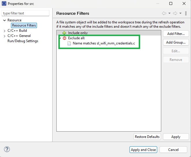
Under ‘components/protocol/wifi/src’, the ‘sl_wifi_nvm_credentials.c’ file should be excluded as shown below.
Under ‘components/service’ only the ‘bsd_socket’ and ‘network_manager’ folders are included with the others excluded as shown below.
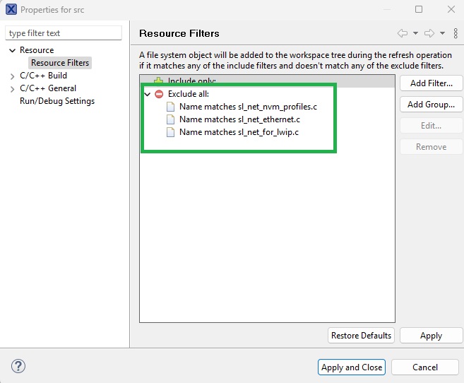
Under ‘components/service/network_manager/src’ the files shown below are excluded.
Adding WiseConnect SDK include paths
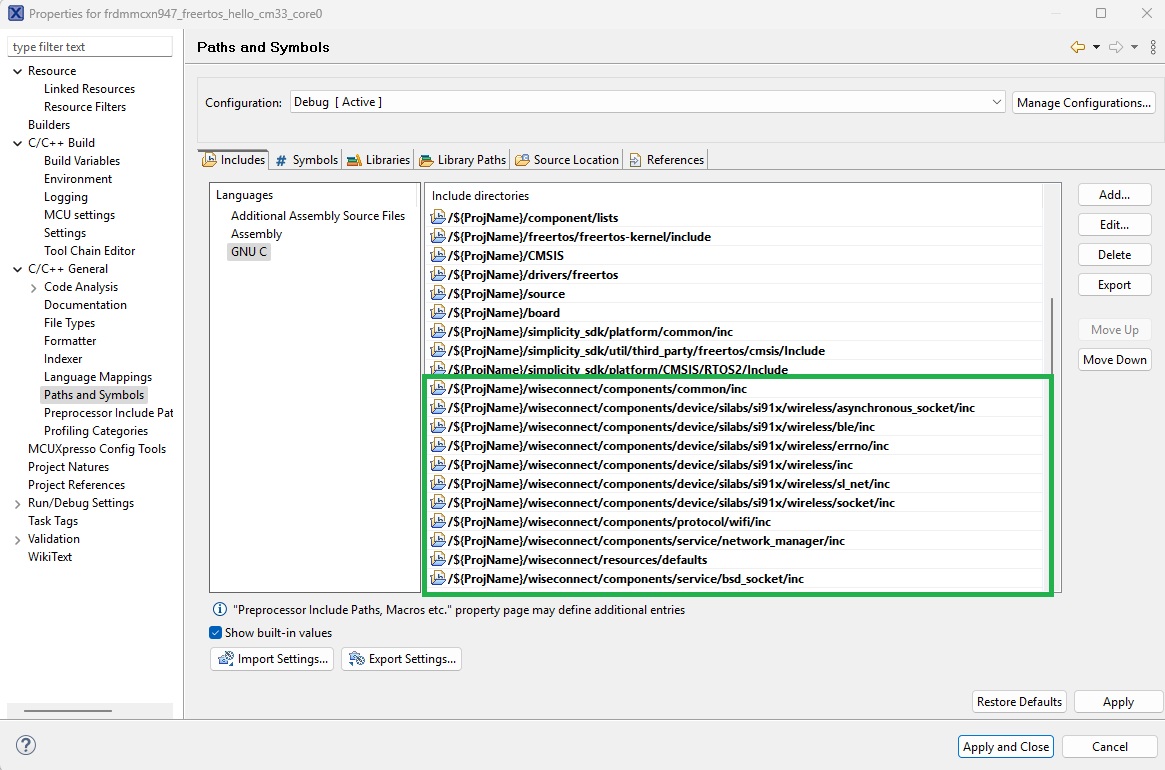
The include paths shown below should be added to the project include paths in the Paths and Symbols dialog.
Adding WiseConnect symbols
The following symbols should be added to the project symbols in the Paths and Symbols dialog.
SLI_SI917                         1
_TIME_T_DECLARED                  1
SLI_SI91X_OFFLOAD_NETWORK_STACK   1
SL_WIFI_COMPONENT_INCLUDED        1
SL_SI91X_ACX_MODULE               1
SLI_SI91X_ENABLE_BLE              1
WiseConnect SDK Workarounds
The file ‘sl_si91x_socket_utility.c’ includes a header file ‘em_core.h'. This file is not available within the MCUXpresso context and will result in build errors. To avoid making modifications to the WiseConnect SDK files, it’s recommended to create a port of the functionality accessed via the em_core.h file within the example application context.
Within the ‘source’ folder at the root level of the example application, an ‘em_core.h’ file should be created. The content of this should be as follows.
#ifndef __EM_CORE__
#define __EM_CORE__

/*******************************************************************************
 *****************************   DEFINES   *************************************
 ******************************************************************************/

#if !defined(CORE_ATOMIC_BASE_PRIORITY_LEVEL)
/** The interrupt priority level disabled within ATOMIC regions. Interrupts
 *  with priority level equal to or lower than this definition will be disabled
 *  within ATOMIC regions. */
#define CORE_ATOMIC_BASE_PRIORITY_LEVEL 3
#endif

/*******************************************************************************
 *************************   TYPEDEFS   ****************************************
 ******************************************************************************/

/// Storage for PRIMASK or BASEPRI value.
typedef uint32_t CORE_irqState_t;

/*******************************************************************************
 *****************************   PROTOTYPES   **********************************
 ******************************************************************************/

/***************************************************************************//**
 * @brief
 *   Exit an ATOMIC section.
 *
 * @param[in] irqState
 *   The interrupt priority blocking level to restore to BASEPRI when exiting
 *   the ATOMIC section. This value is usually the one returned by a prior
 *   call to @ref CORE_EnterAtomic().
 *
 * @note
 *   If @ref CORE_ATOMIC_METHOD is set to @ref CORE_ATOMIC_METHOD_PRIMASK, this
 *   function is identical to @ref CORE_ExitCritical().
 ******************************************************************************/
void  CORE_ExitAtomic(CORE_irqState_t irqState);

/***************************************************************************//**
 * @brief
 *   Enter an ATOMIC section.
 *
 *   When an ATOMIC section is entered, interrupts with priority lower or equal
 *   to @ref CORE_ATOMIC_BASE_PRIORITY_LEVEL are disabled.
 *
 * @note
 *   If @ref CORE_ATOMIC_METHOD is @ref CORE_ATOMIC_METHOD_PRIMASK, this
 *   function is identical to @ref CORE_EnterCritical().
 *
 * @return
 *   The value of BASEPRI register prior to ATOMIC section entry.
 ******************************************************************************/
CORE_irqState_t CORE_EnterAtomic(void);

/***************************************************************************//**
 * @brief
 *   Enter a CRITICAL section.
 *
 *   When a CRITICAL section is entered, all interrupts (except fault handlers)
 *   are disabled.
 *
 * @return
 *   The value of PRIMASK register prior to the CRITICAL section entry.
 ******************************************************************************/
CORE_irqState_t CORE_EnterCritical(void);

/***************************************************************************//**
 * @brief
 *   Exit a CRITICAL section.
 *
 * @param[in] irqState
 *   The interrupt priority blocking level to restore to PRIMASK when exiting
 *   the CRITICAL section. This value is usually the one returned by a prior
 *   call to @ref CORE_EnterCritical().
 ******************************************************************************/
void CORE_ExitCritical(CORE_irqState_t irqState);

/*******************************************************************************
 ************************   MACRO API   ***************************************
 ******************************************************************************/

/// Allocate storage for PRIMASK or BASEPRI value for use by
/// CORE_ENTER/EXIT_ATOMIC() and CORE_ENTER/EXIT_CRITICAL() macros.
#define CORE_DECLARE_IRQ_STATE      CORE_irqState_t irqState

/// Enter CRITICAL section. Assumes that a @ref CORE_DECLARE_IRQ_STATE exist in
/// scope.
#define CORE_ENTER_CRITICAL() irqState = CORE_EnterCritical()

/// Exit CRITICAL section. Assumes that a @ref CORE_DECLARE_IRQ_STATE exist in
/// scope.
#define CORE_EXIT_CRITICAL()  CORE_ExitCritical(irqState)

#endif
An ‘x_core.c’ file should then be created within the ‘source’ folder at the root of the example application folder structure. X should be replaced here with the name of the host MCU, e.g. lpc55s28_core.c, mcxn947_core.c.
This file should include the CMSIS peripheral access layer header file for the host MCU in use. An example implementation for the MCXN947 is shown below.
#include <stdint.h>
#include "em_core.h"
#include "cmsis_gcc.h"
#include "MCXN947_cm33_core0.h"

/***************************************************************************//**
 * @brief
 *   Exit an ATOMIC section.
 * @note
 *   __ISB() makes sure pending interrupts are executed before returning.
 *   This can be a problem if the first instruction after changing the BASEPRI
 *   or PRIMASK assumes that the pending interrupts have already been processed.
 ******************************************************************************/
void CORE_ExitAtomic(CORE_irqState_t irqState)
{
  __set_BASEPRI(irqState);
  __ISB();
}

/***************************************************************************//**
 * @brief
 *   Enter an ATOMIC section.
 ******************************************************************************/
CORE_irqState_t CORE_EnterAtomic(void)
{
  CORE_irqState_t irqState = __get_BASEPRI();
  __set_BASEPRI(CORE_ATOMIC_BASE_PRIORITY_LEVEL << (8U - __NVIC_PRIO_BITS));
  return irqState;
}

/***************************************************************************//**
 * @brief
 *   Enter a CRITICAL section.
 ******************************************************************************/
CORE_irqState_t CORE_EnterCritical(void)
{
  CORE_irqState_t irqState = __get_PRIMASK();
  __disable_irq();
  return irqState;
}

/***************************************************************************//**
 * @brief
 *   Exit a CRITICAL section.
 * @note
 *   __ISB() makes sure pending interrupts are executed before returning.
 *   This can be a problem if the first instruction after changing the BASEPRI
 *   or PRIMASK assumes that the pending interrupts have already been processed.
 ******************************************************************************/
void CORE_ExitCritical(CORE_irqState_t irqState)
{
  if (irqState == 0U) {
    __enable_irq();
    __ISB();
  }
}
Adding Veda SL917 interface drivers in MCUXpresso
As described in the Hardware Overview, either an SPI or UART interface is required to interface to the Veda SL917. In addition, two GPIOs configured by the host MCU as outputs are required as control lines to the Veda SL917. One host MCU GPIO input must configured to generate interrupts on either rising or falling edges.
This section describes how to configure the host MCU GPIOs and select appropriate SDK drivers.
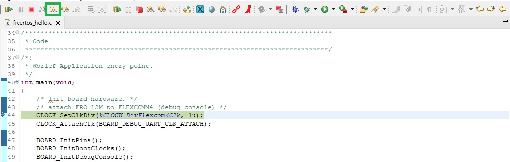
MCUXpresso incorporates Config tools to simplify configuration of the host MCU. The tools are opened via buttons to the top right of the envinronment window. The Pins tool is opened using the button highlighed below. This is used to configure host MCU pin functionality.
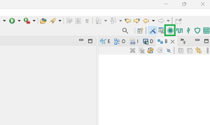
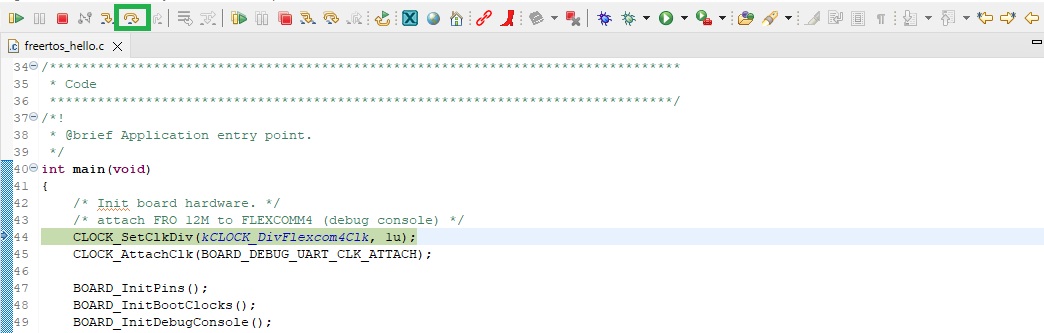
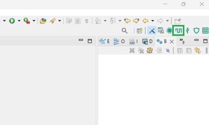
The Clocks tool is used to configure host MCU clocks. It is opened using the button highlighted below.
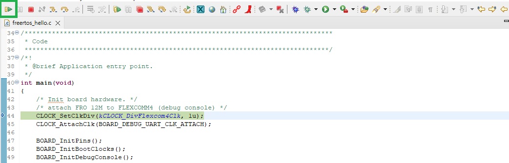
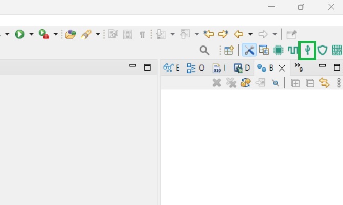
The Peripherals tool is used to configure host MCU peripherals. It is opened using the button highlighted below.
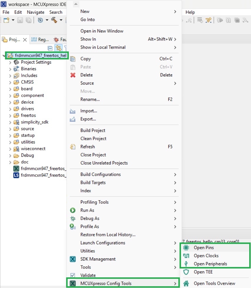
The tools can also be opened by right clicking the name of the project, and selecting one of the tools from the MCUXpresso Config Tools item in the context menu as shown below.
GPIO configuration
Host MCU pins should first be configured. The interface to the Veda SL917 requires the following host MCU pin configurations, working clockwise from the Veda SL917 Click board.
WK - This is a host MCU output. It is used by the host to control the Veda SL917 state, either asleep or awake.
INT - This is a host MCU input that generates interrupts on either rising or falling edges.
TX - This is the Veda SL917 UART transmit pin. If a UART interface is in use, this is a host MCU input to a UART RX pin.
RX - This is the Veda SL917 UART receive pin. If a UART interface is in use, this is a host MCU output from UART TX pin.
SDI - This is the Veda SL917 SPI port receive pin (MOSI/COPI). If an SPI interface is in use, this is a host MCU output from an SPI peripheral MOSI/COPI pin.
SDO - This is the Veda SL917 SPI port transmit pin (MISO/CIPO). If an SPI interface is in use, this is a host MCU input to an SPI peripheral MISO/CIPO pin.
SCK - This is the Veda SL917 SPI port clock pin. If an SPI interface is in use, this is a host MCU output from an SPI peripheral SCK pin.
CS - This is the Veda SL917 Chip Select pin. If an SPI interface is in use, this is a host MCU output from an SPI peripheral CS pin.
RST - This is used to reset the Veda SL917. It is an output from the host MCU.
SLP - This is used by the host to determine the Veda SL917 mode, either asleep or awake. It is an input to the host MCU.
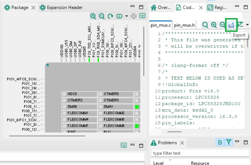
For the LPC55S28-EVK, the Pins tool appears as shown below when opened.
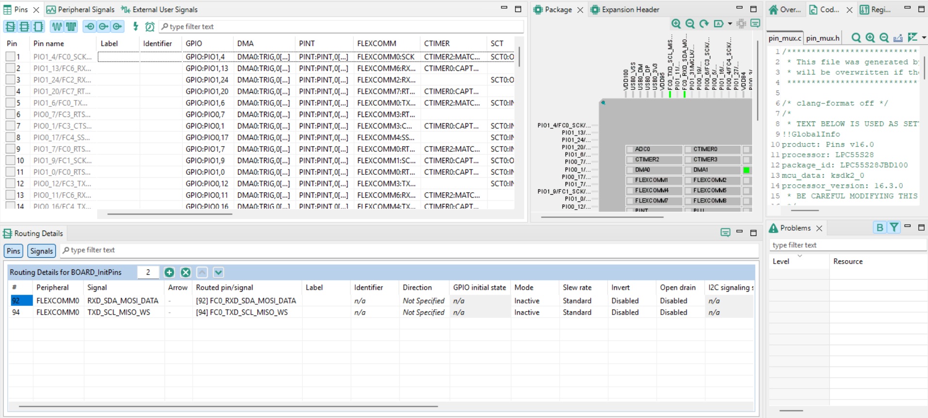
The Pins pane lists the host MCU pins available for configuration. At the foot of the dialog, the Routing Details tab shows pins that have been configured. Note that the debug UART has been allocated here to allow print statements to be output to the serial monitor application.
To the right of the dialog, code generated as a result of changes made to the pin configurations is displayed. This is updated in real time as further changes are made.
To the right of the Routing Details tab, the Problems tab lists configuration related issues that need to be resolved as configuration changes are made.
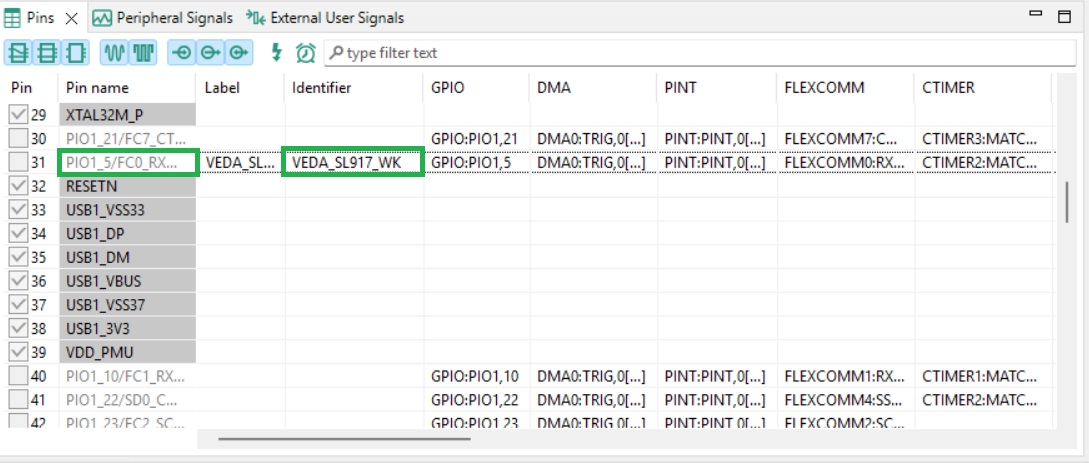
Before configuring a pin, it’s recommended to enter an identifier for the pin. This allows a contextual name to be associated with the pin that is referred to in generated source code, and in later hand written code.
For the LPC55S28-EVK, pins associated with the Veda SL917 interface were identified by cross-referencing with the board schematic, as described in the Interface Identification section.
The WK pin is configured by first entering an identifier in the Identifier column for the appropriate pin, as shown below.
The checkbox to the left of the Pin name is then clicked to determine the pin configuration, as shown below.
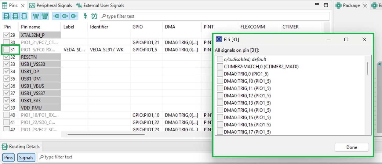
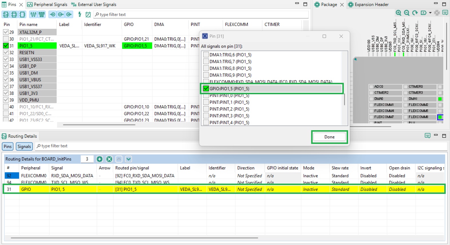
The WK pin needs to be configured as an output GPIO from the host MCU perspective. This option should be located and checked in the Pin dialog, then click Done. Note that when a configuration is set, the Routing Details tab is updated to include the details of the newly configured pin, as shown below.
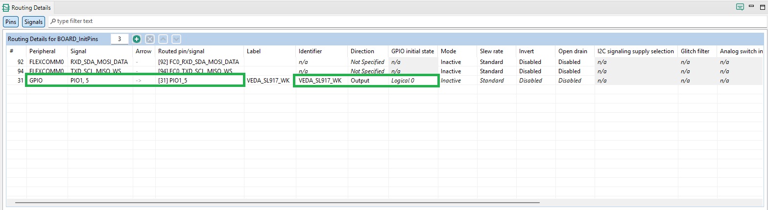
Further pin configuration can now be added for the WK pin. Its Direction is set to Output as shown below, with an initial state of Logic 0.
Generated code is exported the project using the Export button as shown below. Generated code is placed in the ‘board’ folder at the root level of the example project. Generated code should be exported before closing the Pins dialog.
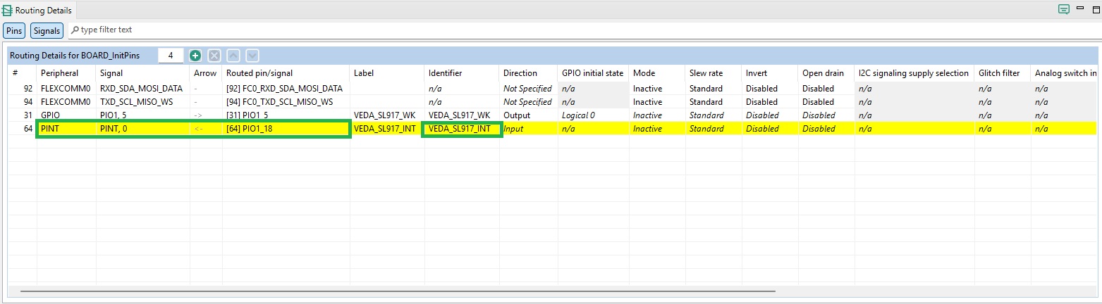
INT pin configuration is shown below.
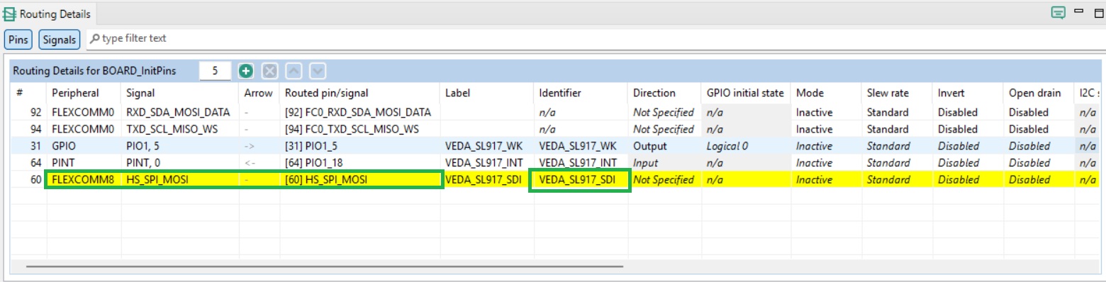
SDI pin configuration is shown below.
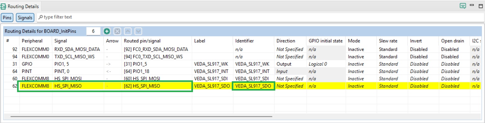
SDO pin configuration is shown below.
SCK pin configuration is shown below.
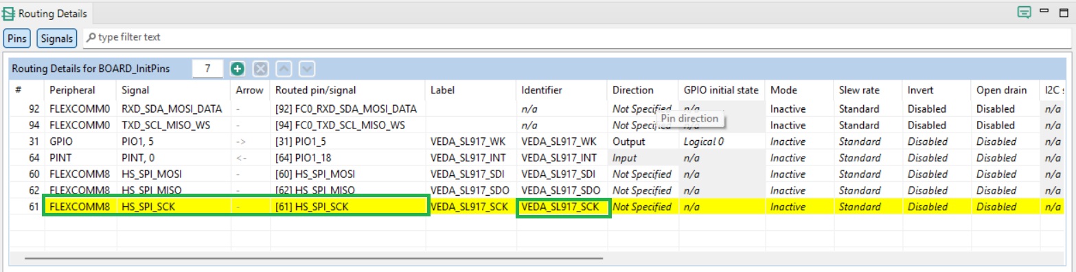
CS pin configuration is shown below.
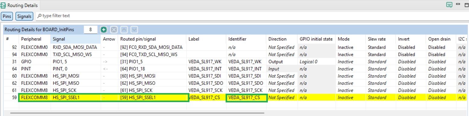
The RESET pin is left unmapped for the LPC55S28-EVK due to being tied to the board Reset button. It should be configured as an Open Drain Output with a default level of Logic High where a GPIO is available.
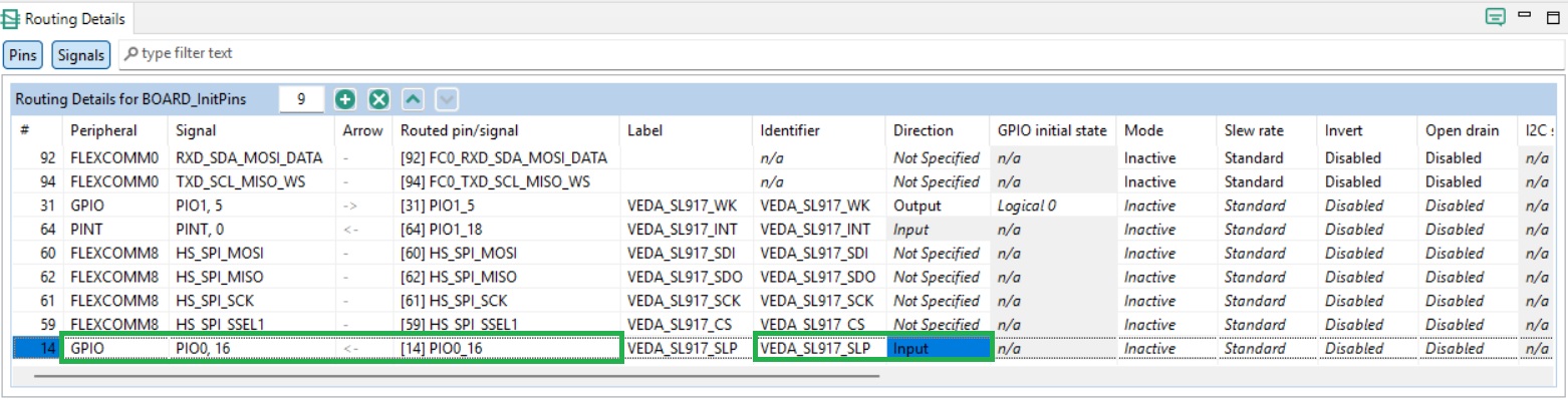
SLP pin configuration is shown below.
Configuring clocks
For the LPC55S28-EVK, the Flexcomm8 peripheral is used for SPI communications. This requires a clock source to be enabled. This is achieved via the Clocks config tool. The Clocks dialog appears as shown below when opened.
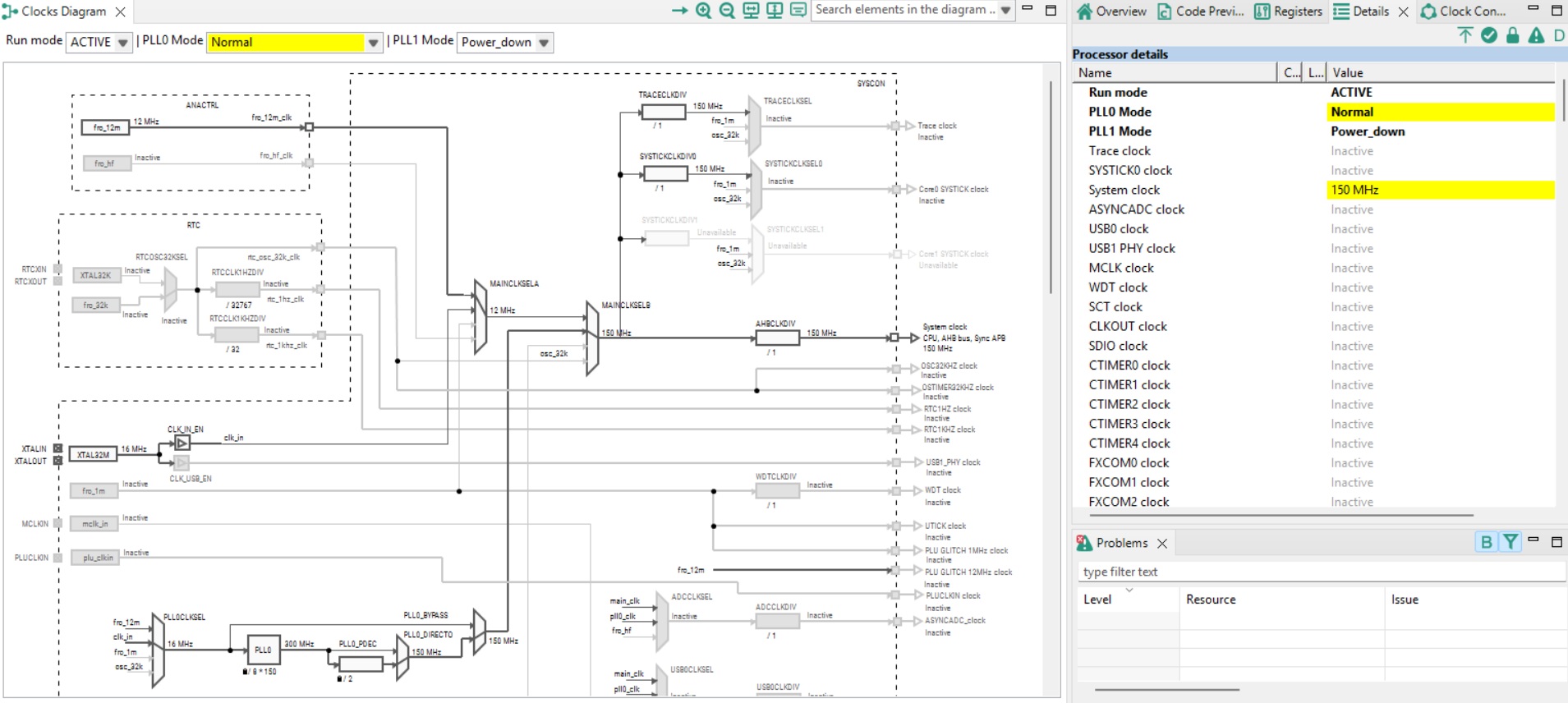
Input clocks are shown to the left of the Clocks Diagram, and output clocks to the right.
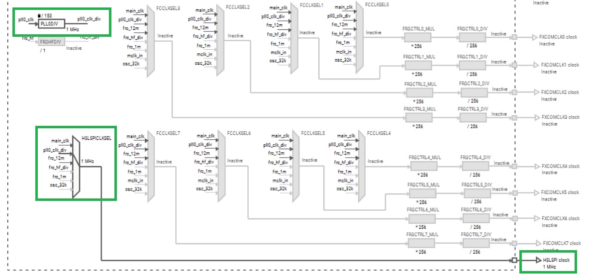
The Flexcomm8 peripheral clock is located at the foot of the Clocks Diagram to the right, as shown below. The highlighted multiplexer is used to determine the input clock source.
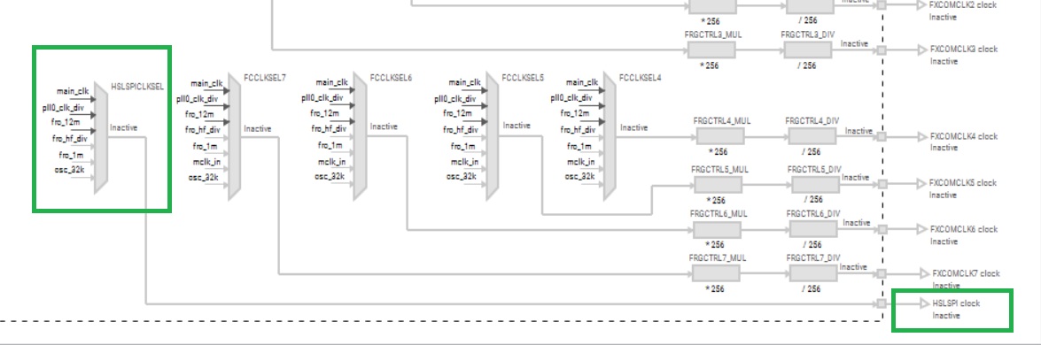
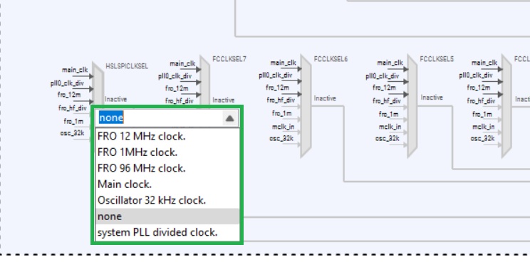
Double-clicking the multiplexer allows the input clock source to be selected as shown below.
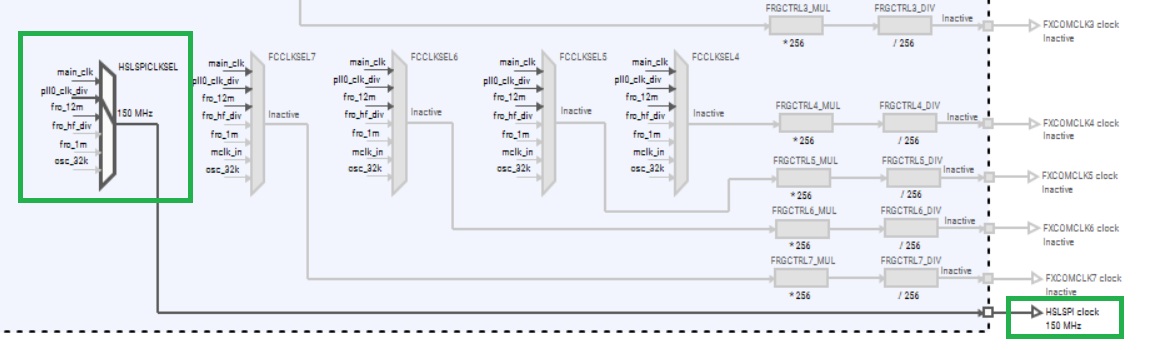
This is set to System PLL divided clock, as shown below. To the right, the clock source is now active at 150MHz.
The clock speed can be reduced by adjusting the PLL0DIV divider as shown below.
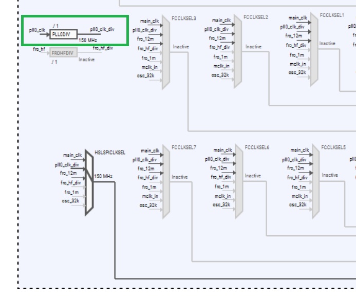
Double clicking the ‘/1’ symbol allows the divider to be set as shown below.
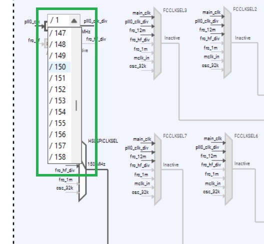
Setting a value of 150 here results in a 1MHz clock being provided to the Flexcomm8 SPI peripheral, as shown below.
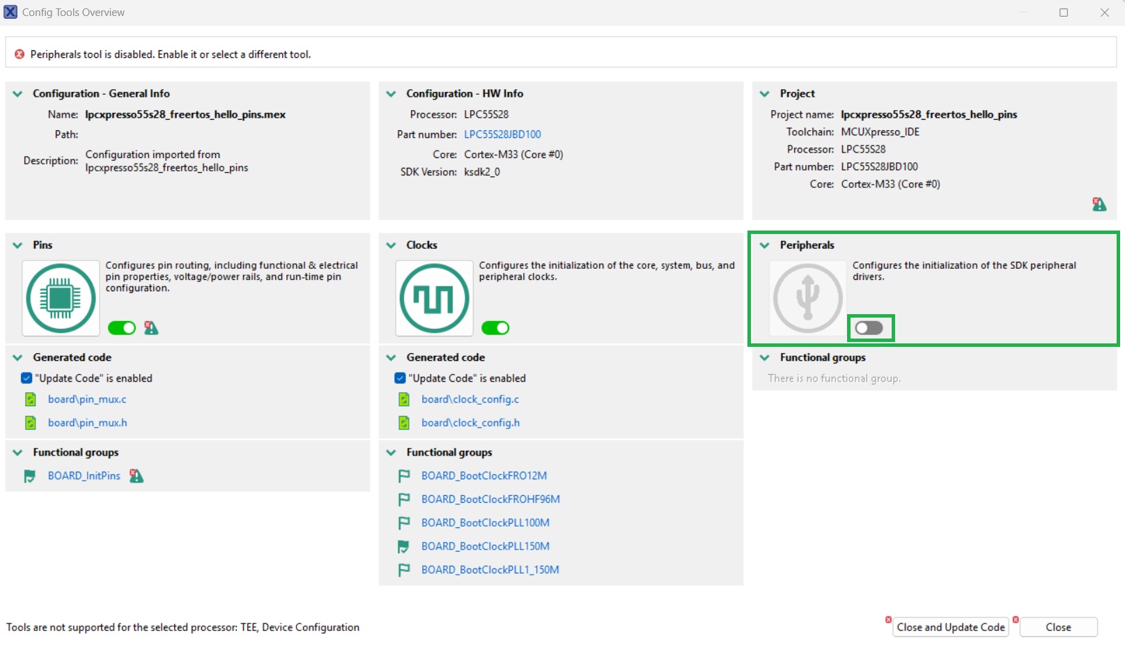
Configuring peripherals
The Peripherals Config tool can now be opened to configure the SPI and PINT peripherals. Upon opening, the dialog shown below may be displayed. The Peripherals Config tool can then be enabled by clicking on the highlighted slider in the Peripherals block.
Once enabled, the Peripherals Config tool appears as shown below. Peripherals available for configuration are shown to the left of the dialog.
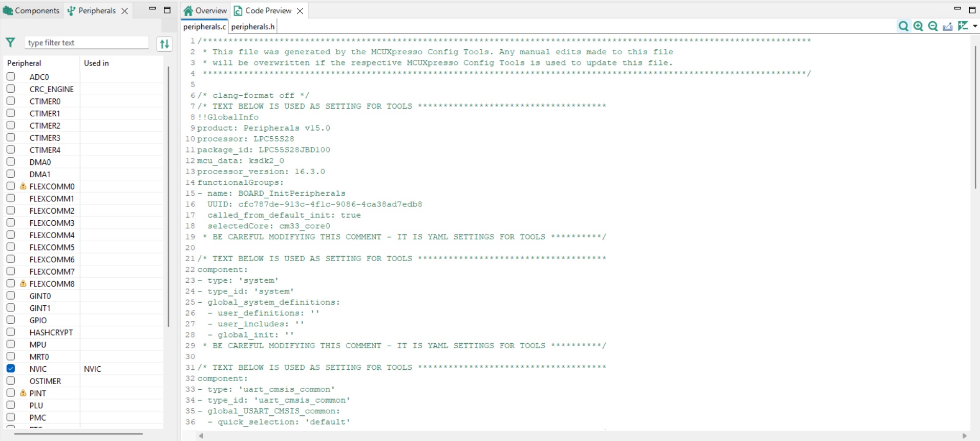
To configure the Flexcomm8 peripheral, tick the checkbox to the left of the peripheral name. This results in the dialog shown below being displayed.
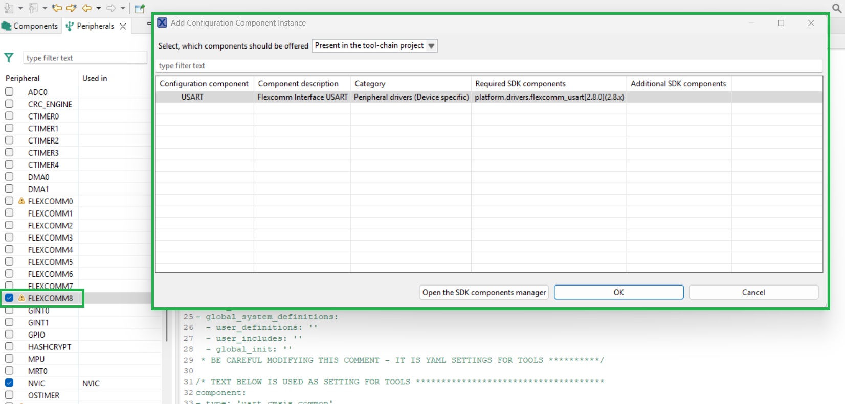
The example application will not have driver code associated with the peripheral installed. To install the driver code, set the ‘Select which components should be offered’ dropdown to ‘Supported by the SDK package’. A list of available drivers is then displayed as shown below.
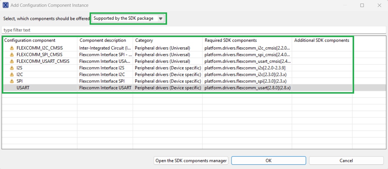
Select the ‘SPI' Configuration component, then click OK.
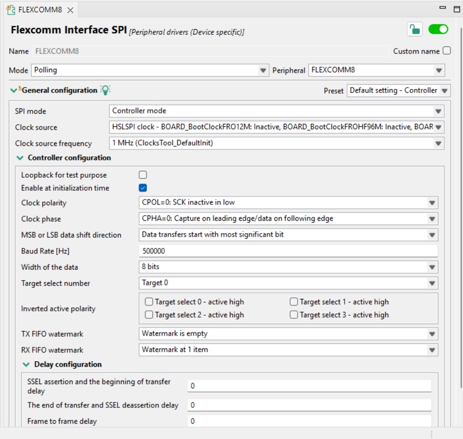
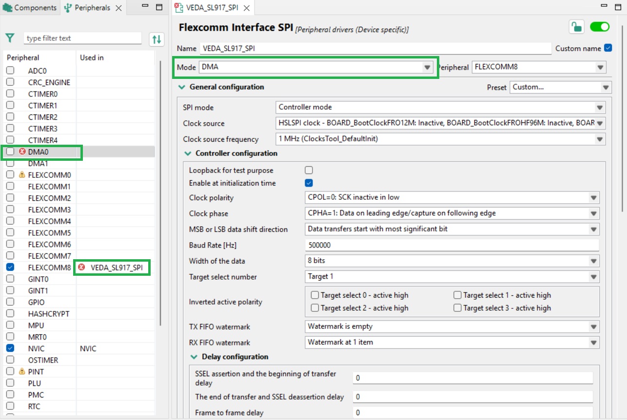
The Flexcomm8 peripheral configuration dialog is then displayed as shown below.
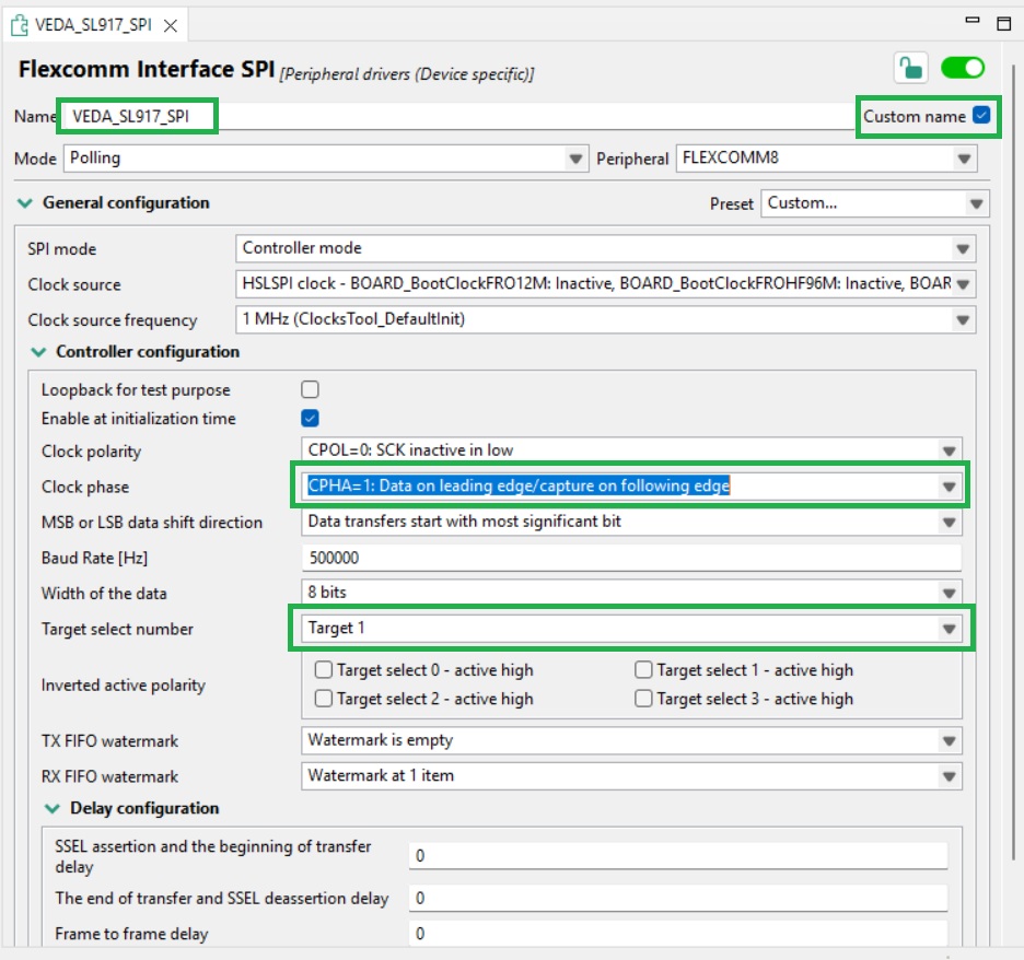
Initial configuration is shown below. Click the custom name checkbox and assign a contextual name to the peripheral. ‘Clock phase’ is set to CPHA = 1. The ‘Target select number’ is used to determine what Chip Select line is used by the peripheral. As Chip Select 1 has been associated with the Veda SL917, this is set to Target 1.
To enable DMA for the SPI interface, add the DMA driver. Setting the SPI peripheral ‘Mode’ to ‘DMA’ results in the SPI configuration dialog being updated as shown below.
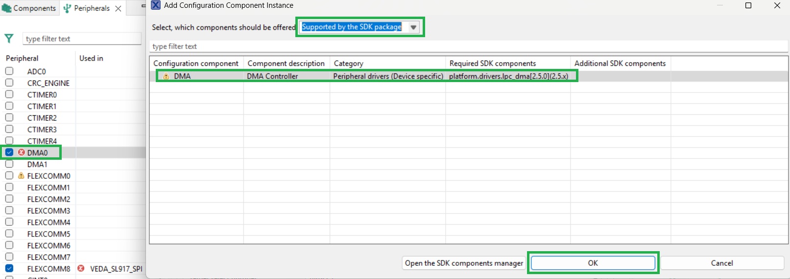
The Peripherals Config tool is warning here that further drivers need to be added. Clicking on the DMA0 peripheral checkbox allows the DMA driver to be installed as shown below.
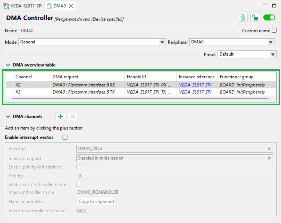
Once installed, the DMA peripheral configuration dialog is displayed as shown below. The SPI peripheral DMA channels are added by the Config Tool, other values can be left at default values.
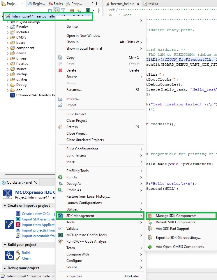
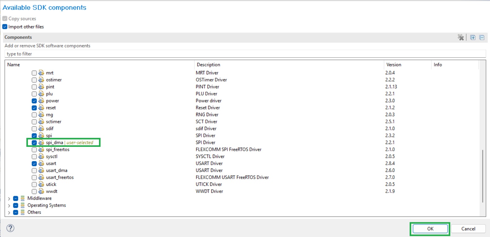
Enabling DMA support for the SPI peripheral requires further drivers to be added. This is performed via the Manage SDK Components dialog. Right click on the project name and select Manage SDK Components from the SDK Management item.
The Available SDK components dialog is then displayed, as shown below. Check the spi_dma component under ‘Drivers’ and click OK to install the driver.
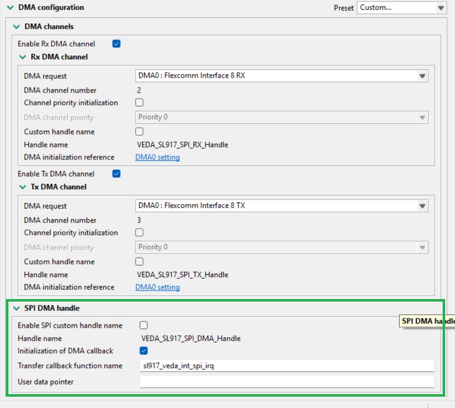
Returning to the SPI peripheral configuration dialog, finalize its configuration as shown below. A callback is added here used to notify the application when an SPI transfer has completed.
You can now export code to the application.
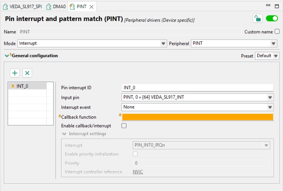
The PINT peripheral must also be configured to generate interrupts from the Veda SL917 INT pin. The checkbox to the left of the peripheral name must be checked and the driver installed.
The peripheral configuration dialog is then displayed as shown below.
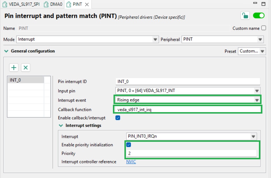
The pin interrupt is then configured as shown below. Note that the Priority assigned to the interrupt must be 2 or greater to avoid conflicting with FreeRTOS interrupts.
From the SDK Components dialog, the ‘pint’ driver should then be installed.
Adding the host MCU integration for the WiseConnect SDK
The WiseConnect SDK invokes host MCU functionality via the interface described in the ‘components/device/silabs/si91x/wireless/host_mcu’ folder. Implementations must be provided for the following functions.
void sl_si91x_host_hold_in_reset(void)
{
  /* Sets the VEDA_SL917 RESET pin to a logic low */
}

void sl_si91x_host_release_from_reset(void)
{
  /* Sets the VEDA_SL917 RESET pin to a logic high */
}

sl_status_t sl_si91x_host_init(const sl_si91x_host_init_configuration *config)
{
  /* Initialises peripherals associated with the VEDA SL917 interface */
}

sl_status_t sl_si91x_host_deinit(void)
{
  /* Deinitialises peripherals associated with the VEDA SL917 interface */
}

sl_status_t sl_si91x_host_spi_transfer(const void *tx_buffer, void *rx_buffer, uint16_t buffer_length)
{
  /* SPI transfer to and from the VEDA SL917 */
}

void sl_si91x_host_enable_high_speed_bus()
{
  /* Enables the VEDA SL917 SPI interface */
}

void sl_si91x_host_enable_bus_interrupt(void)
{
  /* Enables the interrupt associated with the VEDA SL917 INT pin */
}

void sl_si91x_host_disable_bus_interrupt(void)
{
  /* Disables the interrupt associated with the VEDA SL917 INT pin */
}

void sl_si91x_host_set_sleep_indicator(void)
{
  /* Sets the VEDA SL917 WAKE pin */
}

void sl_si91x_host_clear_sleep_indicator(void)
{
  /* Clears the VEDA SL917 WAKE pin */
}

uint32_t sl_si91x_host_get_wake_indicator(void)
{
  /* Reads the state of the VEDA SL917 SLEEP pin */
}

bool sl_si91x_host_is_in_irq_context(void)
{
  /* Determines whether the host in an interrupt context */
}
In the INT pin interrupt handler, the WiseConnect SDK function ‘sli_si91x_set_event’ must be called with an argument of SL_SI91X_NCP_HOST_BUS_RX_EVENT to inform WiseConnect that the interrupt has been triggered.
Porting a WiseConnect Example to the MCUXpresso Project
Example applications are included in the WiseConnect SDK folder ‘examples’. Code in the ‘app.c' file should be copied and pasted into the example application. Configuration files should also be copied into the example application prior to building to ensure all defined symbols are available.