/filters:background_color(white)/2025-01/453-00219%20front4.416.png)
Understanding SoC vs. NCP Mode
The Veda SL917 module offers 2 hardware+firmware options depending on your intended integration path:
- SoC Mode - Integrators develop their firmware application to run directly on the Veda SL917 module using SiLabs Simplicity SDK and WiSeConnect. The SoC operates independently, without an external host.
- NCP Mode - Known as “Network Co-Processor” (NCP) mode, this operating mode is used when an external host microcontroller will control operation of the Veda SL917 module via SPI/UART interface. The SoC provides an API through the WiSeConnect SDK to operate radio functions from the external host.
This guide focuses on the NCP Mode and provides some helpful guidance for use when integrating the Veda SL917 Wi-Fi 6 + BLE module with an external microcontroller as a host.
Hardware Overview
When integrating the Veda SL917 module with an external host MCU, there are 2 interface options to choose from; UART or SPI. For best performance, a SPI bus integration is recommended.
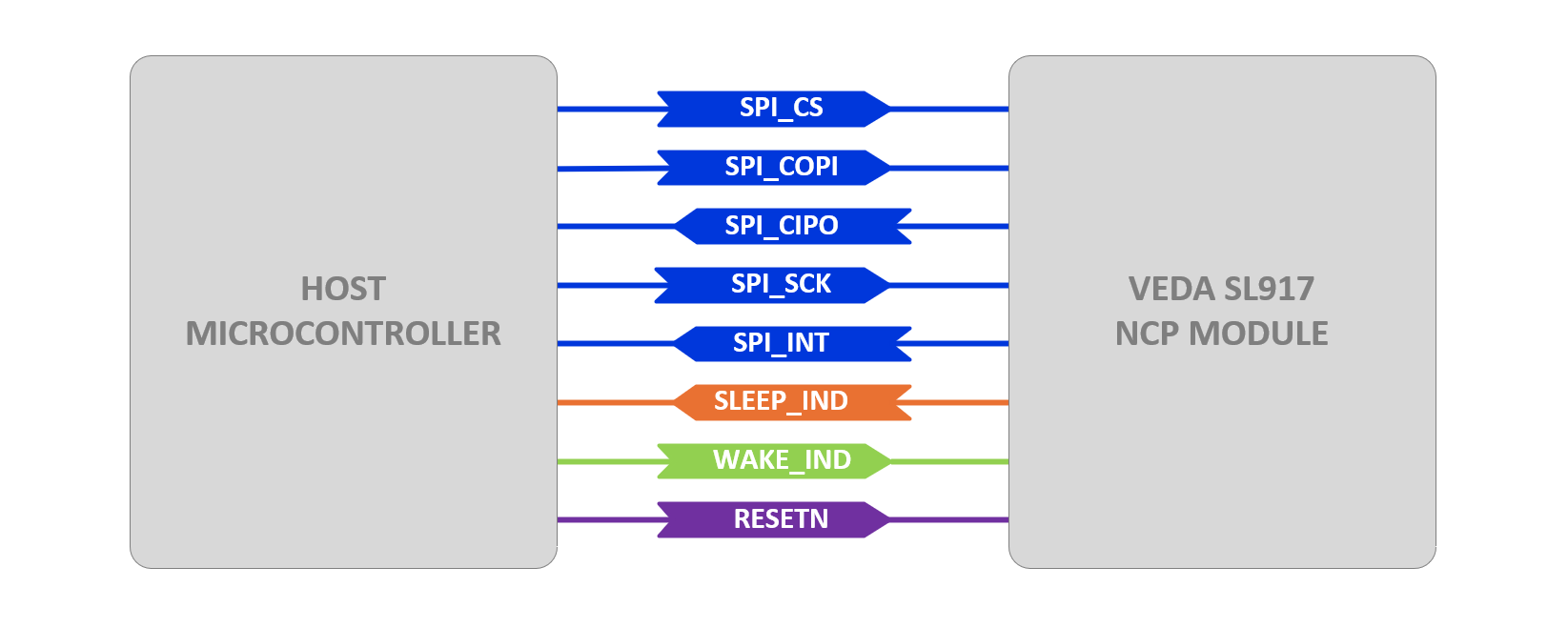
OPTION 1 - SPI INTERFACE
The diagram below shows the minimum required connections between a host microcontroller and the Veda SL917 module when using a SPI bus interface. Note the additional GPIO for reset and sleep signaling.
OPTION 2 - UART INTERFACE
The diagram below shows the minimum required connections between a host microcontroller and the Veda SL917 module when using a UART interface. Note the additional GPIO for reset and sleep signaling.
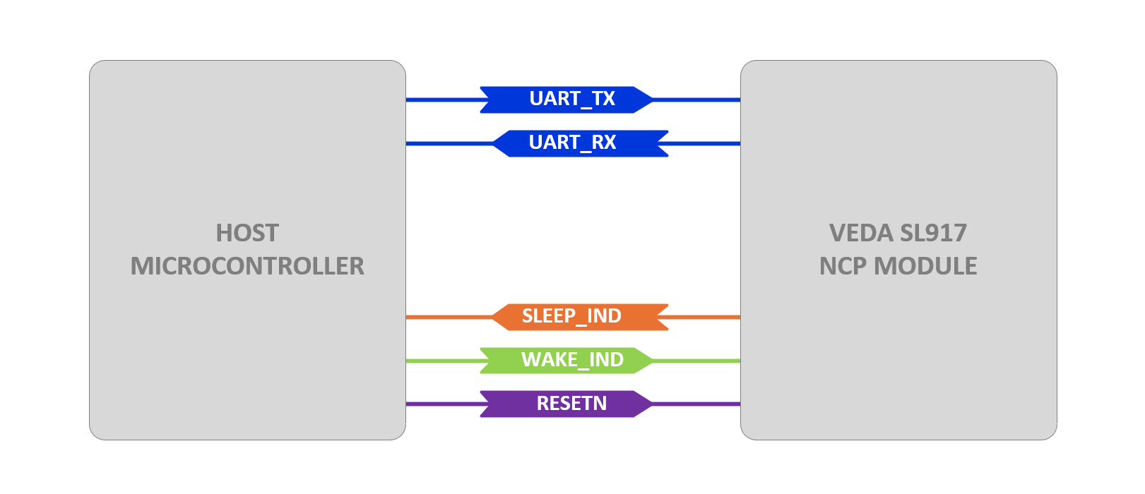
Note that if using the UART interface, some limitations may exist when placing the Veda SL917 module into deep power down modes (for details see release notes in WiSeConnect SDK documentation).
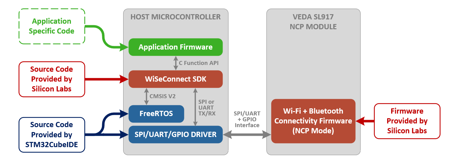
Veda SL917 NCP Mode Software Components
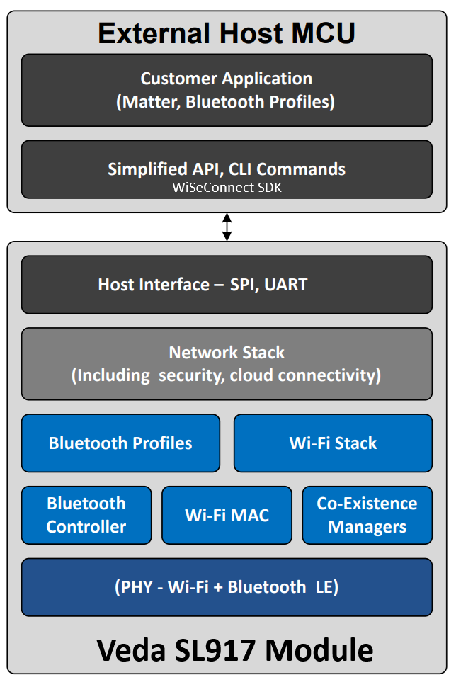
The diagram below provides an overview of the primary software components involved with developing an application with the Veda SL917 module in NCP mode with an external host MCU (e.g., STM32). Details for specific components are outlined below in more detail.
Connectivity Firmware - Veda SL917 Internal Cortex M4 MCU
When operating in NCP mode, the Veda SL917 module runs connectivity firmware on its internal Cortex M4 core designed to provide a SPI/UART interface to an external host to operate the radio functions of the device. The module must first be programmed with this NCP mode connectivity firmware in order to interface with an external host. This firmware is programmed using the ROM bootloader of the Veda SL917 module over a UART connection using the ISP feature.
NCP firmware is provided by Silicon Labs in binary form as an .rps file distributed as part of the WiSeConnect SDK (see theconnectivity_firmware subdirectory of WiSeConnect SDK for details). This .rps firmware image file can be programmed to the Veda SL917 using Simplicity Commander when properly connected to the module via ULP_UART in ISP mode.Example - Programming NCP Firmware on Veda SL917 Click
A convenient way to demonstrate the process of updating the NCP connectivity firmware for Veda SL917 modules is to start with the Veda SL917 Click board manufactured by MIKROE. This board provides a USB-C interface to an FTDI USB-to-serial IC designed to interface with the Veda SL917 module in ISP mode for purposes of programming initial or updating the NCP connectivity firmware.
The following steps are a summarized version of the detailed steps outlined at https://docs.silabs.com/wiseconnect/latest/wiseconnect-getting-started/getting-started-with-ncp-mode-with-stm32
1.) With the Click board on its own (i.e., not installed in a mikroBUS socket of another board), attach the USB-C cable from the Click board to your workstation. Close any terminal application if you have one open for the COM port associated with the USB-C connection on the Click board.
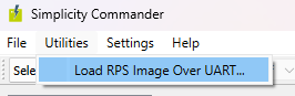
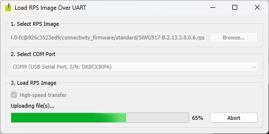
2.) Open the latest version of Simplicity Commander and select Load RPS Image over UART… from the Utilities menu.
3.) Click the “Browse…” button and locate the .rps file from the connectivity_firmware/standard subdirectory of the WiSeConnect SDK.
4.) Click Load RPS and press the RESET button on the click board to reset the bootloader and start uploading the file. You may need to hold the ISP button while resetting to start the bootloader.
5.) Upon successful upload/programming of the connectivity firmware, a dialog will appear.
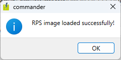
6.) Close Simplicity Commander, the connectivity firmware has now been programmed.
Verifying NCP Firmware is Loaded
To verify that NCP connectivity firmware has been loaded onto the Veda SL917 module, attach the USB-C port to a workstation and open a serial terminal (e.g., PuTTY) at 115200 baud, 8N1. Hold down the ISP button while pressing and releasing the RESET button to enter the bootloader. Type ‘U' into the terminal to access the bootloader menu. Type ‘K’, then '0’ to verify the integrity of the firmware. If wireless firmware is installed properly, after a few seconds of idle time a message will appear indicating it has loaded:
Loading...
AT mode is not supported
Loading DoneValid Firmware Not Present is displayed, follow the steps again for programming NCP firmware onto the NCP module using Simplicity Commander.WiSeConnect SDK - Host MCU API for Wireless Connectivity
The next software component required to run the Veda SL917 module in NCP mode is the WiSeConnect SDK from Silicon Labs. This SDK provides source code designed to compile and run on an external host MCU, providing APIs and driver interface code required for application firmware to control the Wi-Fi and Bluetooth functionality of the radio module.
The WiSeConnect SDK code depends on a CMSIS V2 RTOS interface to the underlying RTOS for event handling and hardware integration with either a SPI or UART driver for communicating with the Veda SL917 module. The diagram below shows the high level architecture of the WiSeConnect SDK software.
See https://github.com/SiliconLabs/wiseconnect/blob/master/docs/software-reference/manuals/siwx91x-software-reference-manual.md#software-architecture for more details on the architecture of the WiSeConnect SDK.
Host MCU SDKs and FreeRTOS - Host MCU Board Support
Lastly, the host MCU requires a vendor-provided set of peripheral drivers for access to SPI or UART bus, GPIO and timers required to develop an application that interacts with the WiSeConnect SDK. This is also where a CMSIS V2 compatible RTOS such as FreeRTOS can be integrated to provide the basis of an application ready to be coupled to the APIs of the WiSeConnect SDK.
Manufacturer-specific Porting Guides
More specific guidance can be found here:
Reviewing the General Porting Process
In review, the use of NCP mode with the Veda SL917 module requires integration of the WiSeConnect SDK into the host microcontroller’s code base and configuration of the physical hardware interface (SPI/UART/GPIO) to provide a command interface. The following is a high-level review of the steps required to include/port the WiSeConnect SDK to your FreeRTOS-based project.
 STEP 1: Create a Starter Project and Configure the Hardware Interface
Create a new project from within the IDE and select your target development board (or at least appropriate host MCU). Use the appropriate pin assignment view of the IDE to select the SPI or UART interface pins to communicate with the Veda SL917 module. Make sure to configure the GPIO appropriately for additional control of the module.
 STEP 2: Programming the Connectivity Firmware
If the Veda SL917 module is not already programmed with appropriate NCP firmware, you may need to use Simplicity Commander to flash the .rps firmware image provided by Silicon Labs that matches the version of WiSeConnect SDK you will be using. The .rps file is distributed with the WiSeConnect SDK in the connectivity_firmware subfolder. The connectivity firmware .rps file can be programmed onto the Veda SL917 when attached to a workstation via the ULP_UART interface using Simplicity Commander. STEP 3: Installing the WiSeConnect SDK
The WiSeConnect SDK is provided in source code form via a Silicon Labs owned GitHub repository and provides the API for the host microcontroller to interface to the Veda SL917 module. In order to build the API into the application firmware, the WiSeConnect SDK must be cloned using git and included in the project as a linked resource. A convenient way to do this is to clone the SDK into the workspace folder of your project and add its path as a linked resource. STEP 4: Add Required Symbols, Include Paths and Exclude Filters
Since the WiSeConnect SDK contains a large number of source code files that may or may not be required by your application firmware, it is important to define appropriate Pre-processor Symbols, Include paths and Exclude Filters to only bring in the required files and resolve build errors. The process for determining the required files may require some trial and error depending on the example project you are trying to build. A good starting point is to setup the station_ping example project to familiarize yourself with the files provided in the WiSeConnect SDK and typical list of Pre-processor Symbols, Include paths and Exclude Filters. STEP 5: Add and Update WiSeConnect Example Files to the Project
Most example projects have an app.c and app.h file that start an application thread to run the example project. Copy the required files into your project’s Core/Inc and Core/Src subfolders and call the app_init() function from main.c to start the example project.There may be several additional callback functions, state handling variables and peripheral configuration setup required. See the station_ping example project walkthrough in this guide for some examples of typical code blocks that may be necessary to add to your project in order to properly enable a WiSeConnect example to run properly. STEP 6: Build and Debug your Project
This step may require some engineering work to ensure appropriate symbols are defined, peripherals are properly configured for your interface (e.g., DMA, SPI, UART, GPIO) and stepping through the WiSeConnect initialization functions to ensure the radio and SDK/stack are starting as expected. Check return codes of functions for clues if the application is not running as expected. Most functions return SL_STATUS_OK on success, so if you notice an error code being returned, be sure to check out the sl_status.h file for a list of the most common error codes to help troubleshoot.Summary
With these steps, you should be well on your way to operating the Veda SL917 module from your host microcontroller.
Additional resources
Silicon Labs Technical Documentation for SiWx917 Wireless SoCs
https://www.silabs.com/support/resources.p-wireless_wi-fi_siwx917-wireless-socs
WiSeConnect SDK on GitHub
https://github.com/SiliconLabs/wiseconnect