/filters:background_color(white)/2025-01/453-00219%20front4.416.png)
Integrating FreeRTOS
For STM32 host microcontrollers, FreeRTOS software components are provided as part of the STM32CubeIDE development environment. When starting a new project, enable the FreeRTOS option.
Creating a Project in STM32CubeIDE
To get started with NCP mode and an STM32 MCU, this guide will walk through typical steps for configuring a project using the STM32CubeIDE from ST Micro. The first step is to create a new project in the STM32CubeIDE configured with FreeRTOS support and appropriate pin mappings for SPI/UART/GPIO interface to the Veda SL917 module. The following sections walk through typical steps for developing a Wi-Fi or Bluetooth enabled application using the STM32CubeIDE. For general documentation on how to use the STM32CubeIDE, refer to the Documentation section of the STM32CubeIDE website.
Required Hardware
For this example, the STM32 NUCLEO-F411RE development board is used as a concrete example of getting a starter project up and running. This section provides details on required hardware to attach the Veda SL917 click board to a NUCLEO-64 board from one of ST Micro’s supported MCU families. Most of these steps can easily be generalized for other NUCLEO-64 based development boards but may vary depending on the hardware and specific microcontroller populated on the NUCLEO-64 board.
Click shield for Nucleo-64
In order to attach the Veda SL917 Click board to an STM32 NUCLEO64 development board, an adapter is required to map the Morpho header pins to a mikroBUS socket. A convenient approach is to use the Click Shield for Nucleo-64 manufactured by MikroE.
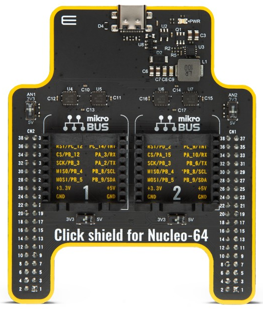
This adapter board connects directly to the Nucleo-64 board via the ST Morpho connectors and provides 2 mikroBUS sockets.
For the Veda SL917 click board, Socket 2 maps to appropriate pins to enable the SPI1 bus from the underlying STM32 MCU to the Veda SL917 module including hardware chip select mapped to PA15.
Attach the Click shield for Nucleo-64 to the Nucleo-64 board, making sure to orient the board per manufacturer’s instructions (the silk screen label “Click shield for Nucleo-64” should be near the push buttons on the Nucleo-64 board, and the USB-C connector should be facing the opposite direction of the micro-USB port on the Nucleo-64 board).
Next, attach the Veda SL917 click board to Socket 2 of the Click shield for Nucleo-64 as seen below:
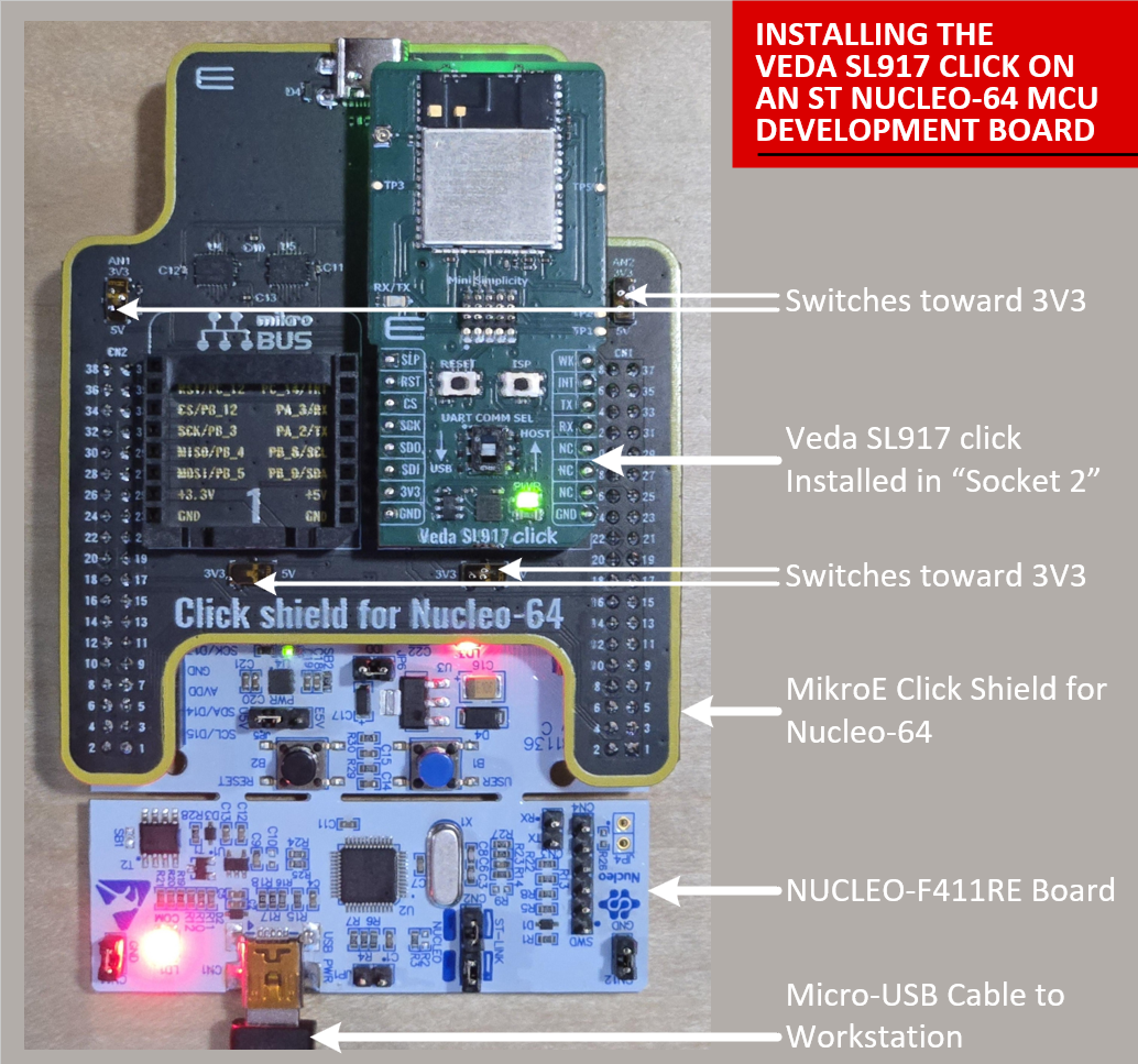
Make sure the micro-switches on the Click shield board are set to 3V3 logic level.
When attaching this configuration to your workstation, use the micro-USB port on the Nucleo-64 board to connect to the workstation. This ensures the ST-Link debugger is detected by the STM32CubeIDE and also provides a Virtual Serial Port connection to the STM32 MCU on USART2 for printf() debug output.
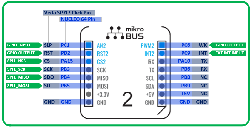
The following diagram shows the pin mapping between the Veda SL917 click board pins on the mikroBUS socket and the corresponding STM32 MCU pins as mapped per the NUCLEO-64 board:
Adding Support for an STM32 MCU Family to STM32CubeIDE
Before creating a project, make sure you have the STM32Cube IDE development environment installed and also have installed the Embedded Software Package for your STM32 Microcontroller. In this case, the STM32 NUCLEO-F411RE board is being used, so the STM32F4 family Embedded Software Package must be added/installed into the STM32CubeIDE environment.
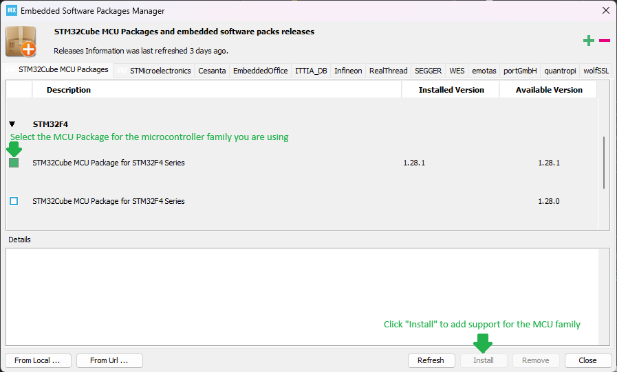
To install an Embedded Software Package, click the Help → Configuration Tool → Manage Embedded Software Packages button from the Help menu.
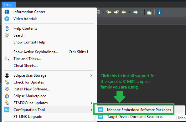
This brings up the Embedded Software Packages Manager window. Scroll down and find the family of the STM32 microcontroller you are working with and expand the line by clicking the “arrow” near the left side of the view. Select the software package with the latest version and click Install to add firmware support into STM32CubeIDE for your microcontroller.
Creating a New “Starter Project”
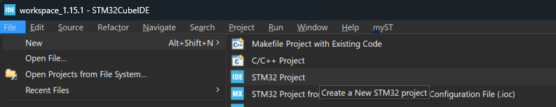
1.) Start by creating a new project in the STM32CubeIDE by clicking “File → New → STM32 Project”.
2.) Click the Board Selector tab and enter the Commercial Part Number for the board you would like to work with. In this example, the NUCLEO-F411RE has been selected:
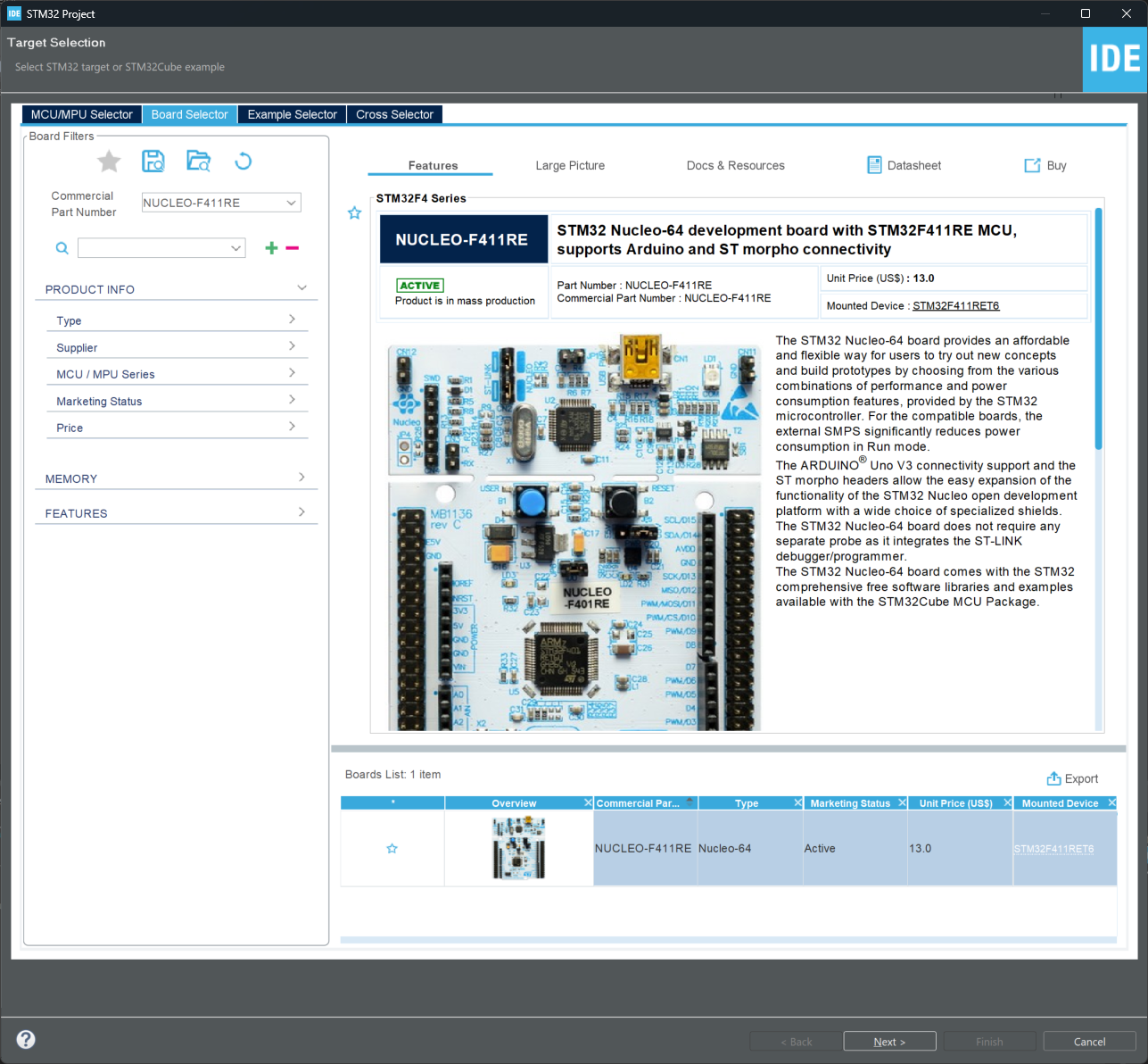
Click the Next > button to continue.
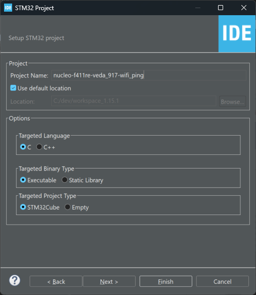
3.) Type a name for your starter project. Leave the remaining options at defaults and click the Next > button to continue.
4.) Leave settings at defaults for the “Firmware Library Package Setup” page and click Finish to continue.
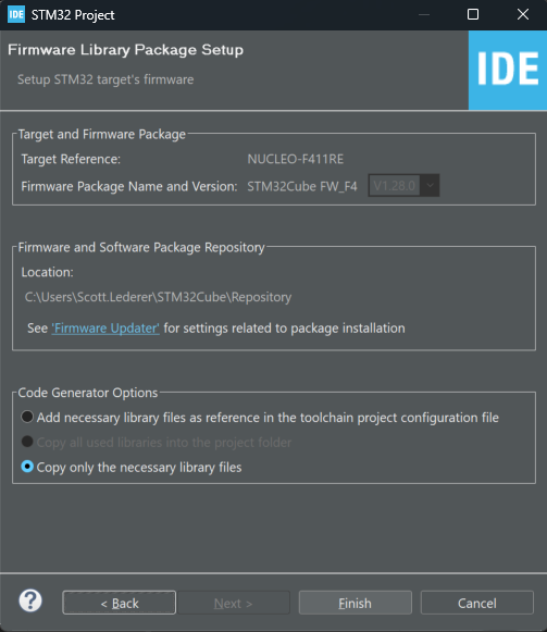
Click Yes on the dialog asking to “Initialize all peripherals with their default Mode?”.
5.) STM32CubeIDE will now generate the initial project and configure peripherals for the board selected in the earlier steps. The Pinout view is displayed allowing review of the pin assignments, peripheral configuration and software packages required for the project. Here is an example of what is displayed for the NUCLEO-F411RE board:
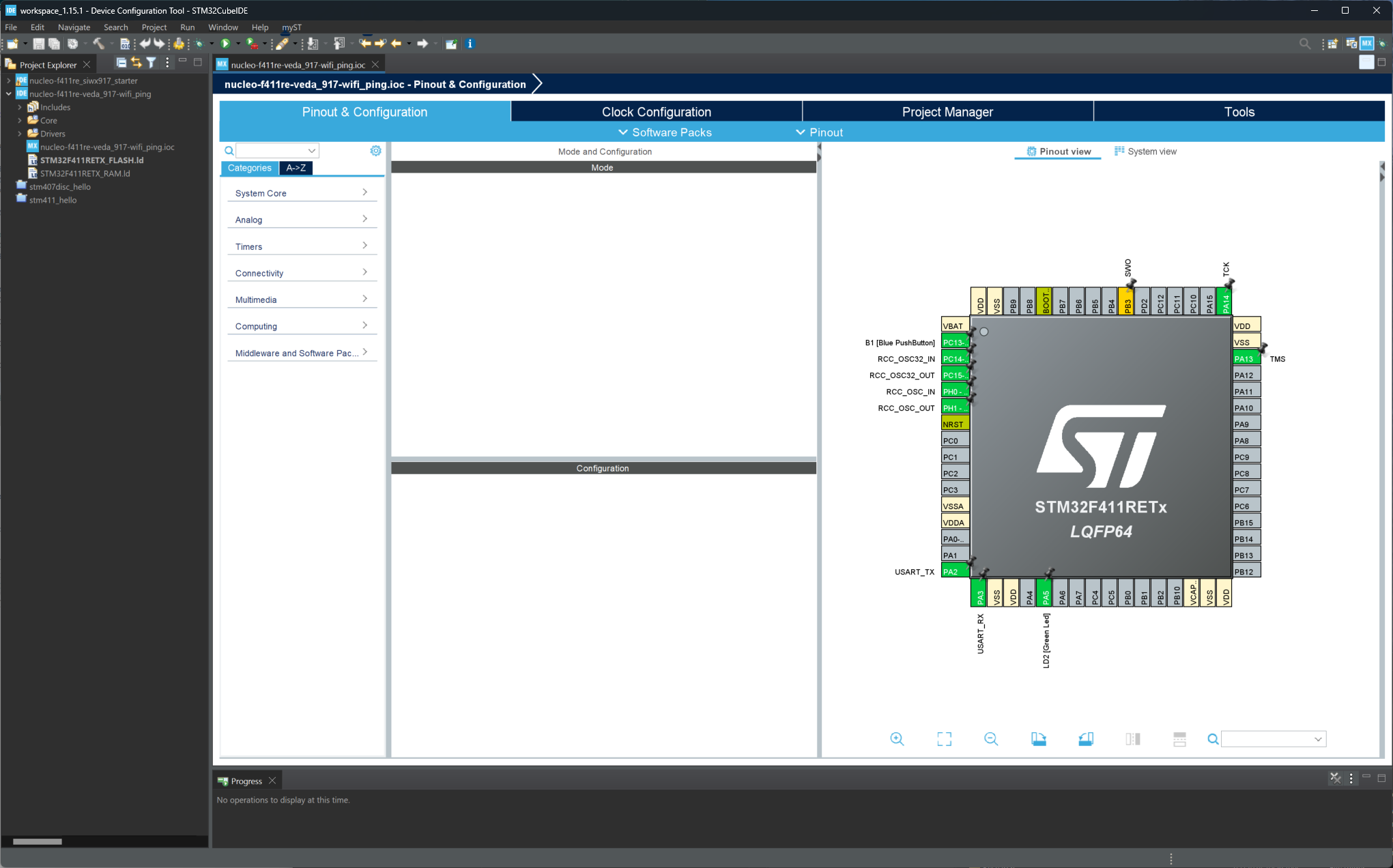
6.) Begin adding the required peripherals to interface with the Veda SL917 module.
Connectivity
SPI1 - Use the Pinout & Configuration view to configure pins and SPI1 peripheral for the project.
Set PB3 to SPI1_SCK function (Click the pin in the pinout view and select SPI1_SCK)
Set PB4 to SPI1_MISO function
Set PB5 to SPI1_MOSI function
In the SPI1 Mode and Configuration panel, set SPI1 Mode to Full-Duplex Master and Hardware NSS Signal to Disable
Set PA15 to GPIO_Output function and configure it in the GPIO category to:
GPIO output level: High
GPIO mode: Output Push Pull
Maximum output speed: Very High
User Label: SL917_CS
Click the DMA Settings tab within the SPI1 Mode and Configuration panel. Click Add to add a DMA stream and select SPI1_RX. Make sure the Mode is set to Normal, Peripheral Increment Address is unchecked, Memory Increment Address is checked, Use Fifo is unchecked and Data Width is set to Byte for both Peripheral and Memory. Click Add again and select SPI1_TX, ensuring the checkboxes for DMA Request Settings match the SPI1_RX settings.
Click the Parameter Settings tab within the SPI1 Mode and Configuration panel. Verify the settings match:
Frame Format: Motorola
Data Size: 8 Bits
First Bit: MSB First
Prescaler (for Baud Rate): 8
Baud Rate: 10.5 MBits/s
Clock Polarity (CPOL): Low
Clock Phase (CPHA): 1 Edge
CRC Calculation: Disabled
NSS Signal Type: Software
Middleware and Software Packs
Click FreeRTOS and set Interface to CMSIS_V2. In the tabs under Configuration, make the following changes:
Config parameters
Memory management settings → TOTAL_HEAP_SIZE: 51200 Bytes
Software timer definitions → TIMER_TASK_PRIORITY: 55
Added with 10.2.1 support → USE_POSIX_ERRNO: Enabled
Advanced Settings
USE_NEWLIB_REENTRANT: Enabled
Click System view and then click SYS. Change the Timebase Source from SysTick to TIM1 hardware timer.
NOTE: Preempt priorities may need to be corrected to a value of 5 depending on FreeRTOS configuration settings. The IDE may prompt you and auto-correct this.
System Core
GPIO - Add the following GPIO entries to define additional control lines between the STM32 MCU and Veda SL917 module
PD2
GPIO Output Level High
Output Open Drain
No pull-up and no pull-down
Maximum output speed: Low
User Label: SL917_RESETN
PC6
GPIO Output Level Low
Output Push-Pull
No pull-up and no pull-down
Maximum output speed: Low
User Label: SL917_WAKE_REQUEST
PC1
Input mode
No pull-up and no pull-down
User Label: SL917_SLEEP_INDICATOR
PC9
External Interrupt Mode with Rising edge trigger detection (click pin in Pinout View and select GPIO_EXTI9)
No pull-up and no pull-down
User Label: SL917_SPI_INT
NVIC
Check the Enabled checkbox for EXTI line[9:5] interrupts to enable interrupts on PC9
Make sure to check the box in the column Uses FreeRTOS function to ensure pre-emption works properly with FreeRTOS
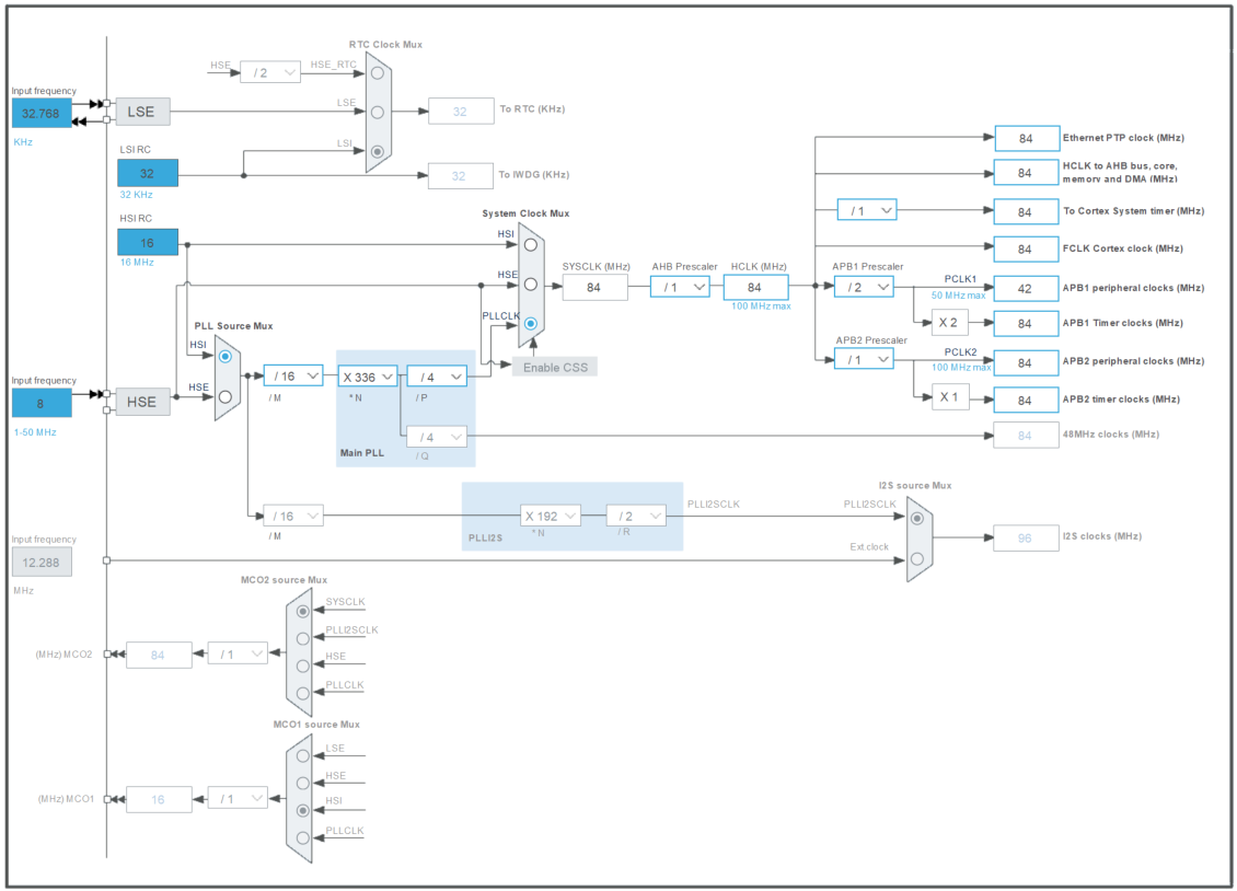
7.) When setting up the Nucleo-F411RE board in STM32CubeIDE, the default setting for clocks can be used. Here is a snapshot of the settings used in this example for reference:
8.) Click Save to save the project and generate the project source code. Select Yes on the Do you want to generate Code? dialog. At the Open Associated Perspective? dialog, click No to continue. Once the code generation is finished, open the main.c file from the Project Explorer tab on the left-hand side of the window to browse the generated project code.
Testing the Starter Project
At this point, the project can be built and executed on the target board. The code doesn’t do much of anything other than initialize some peripherals and start a FreeRTOS task that runs in an infinite loop with a 1ms delay.
To verify the project is valid at this point, run a build by typing Ctrl+B or by selecting “Project → Build” from the menu. The Console tab near the bottom of the STM32CubeIDE window should show that the Build Finished with 0 errors, 0 warnings.
Adding printf() for Debug Output
A useful feature to get working early on with any development environment is the ability to print debug output to the console. In the case of the NUCLEO-F411RE board, a Virtual COM Port is available on the USB interface attached to the USART2 peripheral.
To enable printf() for printing output to the Virtual COM port, do the following:
1.) Open the main.c file from the project and locate the comment containing USER CODE BEGIN Includes. On the line immediately after this comment, enter #include "stdio.h" to bring in the standard i/o library header.
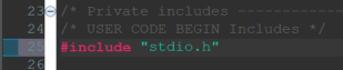
Remember that the STM32CubeIDE provides a code generator that builds peripheral initialization and interrupt handler functions automatically for you based on the initial setup in the pin configuration tool. It is important to remember to only add code in designated sections of such generated files (e.g., main.c). These sections are found in between comments that are labeled USER CODE BEGIN and USER CODE END. Only adding code in these sections will ensure code you add/modify is maintained if/when changes are made to the pin configuration tool and project code is re-generated.
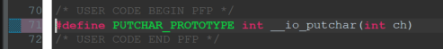
2.) Next, define the PUTCHAR_PROTOTYPE macro that can be used to re-target the built-in __io_putchar function. Enter the following code immediately after the comment line containing USER CODE BEGIN PFP:
#define PUTCHAR_PROTOTYPE int __io_putchar(int ch)When finished, the code will look something like this:
3.) Finally, add the following section of code between USER CODE BEGIN 4 and USER CODE END 4 comments in main.c:
/**
  * @brief  Retargets the C library printf function to the USART.
  * @Param  None
  * @retval None
  */
PUTCHAR_PROTOTYPE
{
  /* Place your implementation of fputc here */
  /* e.g. write a character to the USART1 and Loop until the end of transmission */
  HAL_UART_Transmit(&huart2, (uint8_t *)&ch, 1, 0xFFFF);

  return ch;
}
4.) Now that printf() has been enabled, modify the void StartDefaultTask(void *argument) function by replacing the contents of code between USER CODE BEGIN 5 and USER CODE END 5 with the following:
/* Infinite loop */
  for(;;)
  {
	printf("Hello from FreeRTOS!\r\n");
    osDelay(2000);
  }
5.) Build the project by typing Ctrl+B or selecting “Project → Build All”.
6.) Attach the Nucleo board USB port to your workstation and test out your build by clicking the Run → Debug menu option. If this is the first time you are running a project, you’ll need to click the Debugger tab and select ST-Link S/N as your debugger. If the field is empty, click Scan with your board attached and it should fill in the serial number automatically. You can click OK to apply settings and attempt to program and run the firmware on your board.
The tool will program the firmware, then drop you into a debug session at HAL_Init(); in main.c. You can use the debugger perspective buttons near the top of the window to control the debug session. Press the green “Play” button to continue running the application (or type the F8 key). Open a serial terminal attached to the USB port associated with your board (115200 baud, 8N1). You should see a periodic log output printing Hello from FreeRTOS!on your serial terminal if the firmware is running as expected.
Adding Support for Veda SL917
Now that you’ve successfully configured a starter project with the proper peripherals configured to interface to the Veda SL917 radio module, it is time to import the required SDK files and example source code into your project.
Clone the WiSeConnect SDK
Start by using git to clone the WiSeConnect SDK repository from https://github.com/SiliconLabs/wiseconnect into your STM32CubeIDE workspace folder (i.e., the folder one level above your STM32CubeIDE project folder). This will create a folder named wiseconnect in parallel to your project folder created in previous steps. When done this way, multiple projects can reference the same copy of WiSeConnect source code as a “linked resource” rather than making a copy for every project.
Adding WiSeConnect SDK to the Project as a Linked Resource
To add WiSeConnect SDK to your STM32CubeIDE project as a Linked Resource and define the project files you’ll need to include in order to develop a Wi-Fi/BLE project, take the following steps:
1.) Within STM32CubeIDE, right-click the project root in the Project Explorer and click Close Project.
2.) Next, with a text editor such as VS Code, open the .project file in the project folder for your STM32CubeIDE project. This is an XML file that defines the name of the project along with some simple configuration values. On the line right above </projectDescription>, add the following section of XML to link in the wiseconnect folder from your workspace into the Middlewares/ThirdParty/wiseconnect path in your project tree:
LINKED RESOURCES
<linkedResources>
		<link>
			<name>Middlewares/Third_Party/wiseconnect</name>
			<type>2</type>
			<locationURI>WORKSPACE_LOC/wiseconnect</locationURI>
		</link>
	</linkedResources>
Notice how the environment variable WORKSPACE_LOC is used to locate the wiseconnect folder. This must match the location you used git to clone the WiSeConnect SDK files.
Adding Symbols, Include Paths and Exclude Lists
Now that the WiSeConnect SDK folder is referenced by the project, the next step is to add required pre-processor symbols, include paths and exclude filters to bring in the desired files for the project. The exclude filters are important to prevent source code files not required by your project from being built and potentially causing unexpected build errors.
With a text editor such as VS Code, open the .cproject file in the project folder for your STM32CubeIDE project. This is an XML file that defines the project configuration.
The Symbols, Include Paths and Exclude Filters listed in this guide are specific to getting the wiseconnect/examples/snippets/wlan/station_ping example from WiSeConnect 3 SDK up and running and may not reflect the full set of Symbols/Include Paths/Exclude Filters needed for other WiSeConnect example projects. For more details on a specific WiSeConnect example and its requirements, refer to the README.md included within the example folder under the appropriate wiseconnect/examples/* subfolder.
SYMBOLS
Add the following <listOptionValue> items to the Debug and Release "<configuration>" elements under
<tool id="com.st.stm32cube.ide.mcu.gnu.managedbuild.tool.c.compiler.907838932" name="MCU GCC Compiler" superClass="com.st.stm32cube.ide.mcu.gnu.managedbuild.tool.c.compiler">
<option IS_BUILTIN_EMPTY="false" IS_VALUE_EMPTY="false" id="com.st.stm32cube.ide.mcu.gnu.managedbuild.tool.c.compiler.option.definedsymbols.913367554" name="Define symbols (-D)" superClass="com.st.stm32cube.ide.mcu.gnu.managedbuild.tool.c.compiler.option.definedsymbols" useByScannerDiscovery="false" valueType="definedSymbols">
<listOptionValue builtIn="false" value="SL_SI91X_ACX_MODULE=1"/>
<listOptionValue builtIn="false" value="SLI_SI91X_ENABLE_BLE=1"/>
<listOptionValue builtIn="false" value="SL_SI91X_ENABLE_LITTLE_ENDIAN=1"/>
<listOptionValue builtIn="false" value="SL_CATALOG_FREERTOS_KERNEL_PRESENT"/>
<listOptionValue builtIn="false" value="SL_SI91X_PRINT_DBG_LOG"/>
<listOptionValue builtIn="false" value="SLI_SI917B0=1"/>
<listOptionValue builtIn="false" value="SLI_SI91X_MCU_CONFIG_RADIO_BOARD_VER2=1"/>
<listOptionValue builtIn="false" value="SL_NET_COMPONENT_INCLUDED=1"/>
<listOptionValue builtIn="false" value=""__STATIC_INLINE=static inline""/>
<listOptionValue builtIn="false" value="SLI_SI917=1"/>
<listOptionValue builtIn="false" value="SL_WIFI_COMPONENT_INCLUDED=1"/>
<listOptionValue builtIn="false" value="HARDWARE_BOARD_DEFAULT_RF_BAND_2400=1"/>
<listOptionValue builtIn="false" value="HARDWARE_BOARD_SUPPORTS_1_RF_BAND=1"/>
<listOptionValue builtIn="false" value="HARDWARE_BOARD_SUPPORTS_RF_BAND_2400=1"/>
<listOptionValue builtIn="false" value="configNUM_SDK_THREAD_LOCAL_STORAGE_POINTERS=2"/>
<listOptionValue builtIn="false" value="SLI_SI91X_SOCKETS=1"/>
<listOptionValue builtIn="false" value="SLI_SI91X_OFFLOAD_NETWORK_STACK=1"/>
<listOptionValue builtIn="false" value="SL_SI91X_SPI_HIGH_SPEED_ENABLE"/>
<listOptionValue builtIn="false" value="SL_CATALOG_KERNEL_PRESENT"/>INCLUDE PATHS
Add the following to the Debug and Release "<configuration>" elements under
<option IS_BUILTIN_EMPTY="false" IS_VALUE_EMPTY="false" id="com.st.stm32cube.ide.mcu.gnu.managedbuild.tool.c.compiler.option.includepaths.1671571650" name="Include paths (-I)" superClass="com.st.stm32cube.ide.mcu.gnu.managedbuild.tool.c.compiler.option.includepaths" useByScannerDiscovery="false" valueType="includePath">
<listOptionValue builtIn="false" value=""${workspace_loc:/${ProjName}/Middlewares/Third_Party/wiseconnect/components/service/bsd_socket/inc}""/>
<listOptionValue builtIn="false" value=""${workspace_loc:/${ProjName}/Middlewares/Third_Party/wiseconnect/components/service/network_manager/inc}""/>
<listOptionValue builtIn="false" value=""${workspace_loc:/${ProjName}/Middlewares/Third_Party/wiseconnect/components/device/silabs/si91x/wireless/errno/inc}""/>
<listOptionValue builtIn="false" value=""${workspace_loc:/${ProjName}/Middlewares/Third_Party/wiseconnect/components/device/silabs/si91x/wireless/icmp}""/>
<listOptionValue builtIn="false" value=""${workspace_loc:/${ProjName}/Middlewares/Third_Party/wiseconnect/components/device/silabs/si91x/wireless/firmware_upgrade}""/>
<listOptionValue builtIn="false" value=""${workspace_loc:/${ProjName}/Middlewares/Third_Party/wiseconnect/components/device/silabs/si91x/wireless/ncp_interface/uart}""/>
<listOptionValue builtIn="false" value=""${workspace_loc:/${ProjName}/Middlewares/Third_Party/wiseconnect/components/device/silabs/si91x/wireless/inc}""/>
<listOptionValue builtIn="false" value=""${workspace_loc:/${ProjName}/Middlewares/Third_Party/wiseconnect/components/device/silabs/si91x/wireless/ble/inc}""/>
<listOptionValue builtIn="false" value=""${workspace_loc:/${ProjName}/Middlewares/Third_Party/wiseconnect/components/device/silabs/si91x/wireless/sl_net/inc}""/>
<listOptionValue builtIn="false" value=""${workspace_loc:/${ProjName}/Middlewares/Third_Party/wiseconnect/components/protocol/wifi/inc}""/>
<listOptionValue builtIn="false" value=""${workspace_loc:/${ProjName}/Middlewares/Third_Party/wiseconnect/resources/certificates}""/>
<listOptionValue builtIn="false" value=""${workspace_loc:/${ProjName}/Middlewares/Third_Party/wiseconnect/resources/html}""/>
<listOptionValue builtIn="false" value=""${workspace_loc:/${ProjName}/Middlewares/Third_Party/wiseconnect/components/common/inc}""/>
<listOptionValue builtIn="false" value=""${workspace_loc:/${ProjName}/Middlewares/Third_Party/wiseconnect/resources/other}""/>
<listOptionValue builtIn="false" value=""${workspace_loc:/${ProjName}/Middlewares/Third_Party/wiseconnect/components/device/silabs/si91x/wireless/socket/inc}""/>
<listOptionValue builtIn="false" value=""${workspace_loc:/${ProjName}/Middlewares/Third_Party/wiseconnect/components/device/stm32/silabs_utility/common/inc}""/>
<listOptionValue builtIn="false" value=""${workspace_loc:/${ProjName}/Middlewares/Third_Party/wiseconnect/components/device/stm32/silabs_utility}""/>EXCLUDE FILTERS
Replace the "Middlewares" entry in the <sourceEntries> sections of the Debug and Release "<configuration>" elements right below the last <fileInfo> tag and before </configuration>
    <sourceEntries>
        <entry excluding="Third_Party/wiseconnect/components/service/sl_websocket_client|Third_Party/wiseconnect/components/device/silabs/si91x/wireless/host_mcu|Third_Party/wiseconnect/components/protocol/wifi/src/sl_wifi_nvm_credentials.c|Third_Party/wiseconnect/components/service/sl_web_socket_client|Third_Party/wiseconnect/components/device/silabs/si91x/wireless/ncp_interface/uart|Third_Party/wiseconnect/components/device/silabs/si91x/wireless/memory/static_buffer.c|Third_Party/wiseconnect/components/device/silabs/si91x/wireless/memory/mem_pool_buffers.c|Third_Party/wiseconnect/components/device/silabs/si91x/wireless/memory/mem_pool_buffer_quota.c|Third_Party/wiseconnect/components/device/silabs/si91x/wireless/memory/lwip_buffers.c|Third_Party/wiseconnect/components/service/network_manager/src/sl_net_nvm_profiles.c|Third_Party/wiseconnect/components/service/network_manager/src/sl_net_nvm_credentials.c|Third_Party/wiseconnect/components/service/network_manager/src/sl_net_for_lwip.c|Third_Party/wiseconnect/components/service/network_manager/src/sl_net_ethernet.c|Third_Party/wiseconnect/components/service/network_manager/inc/sl_net_for_lwip.h|Third_Party/wiseconnect/components/device/silabs/si91x/wireless/src/sl_si91x_http_client_callback_framework.c|Third_Party/wiseconnect/resources/scripts|Third_Party/wiseconnect/resources/lwip_defaults|Third_Party/wiseconnect/resources/defaults|Third_Party/wiseconnect/components/service/sntp|Third_Party/wiseconnect/components/service/sl_http_server|Third_Party/wiseconnect/components/service/mqtt|Third_Party/wiseconnect/components/service/mdns|Third_Party/wiseconnect/components/service/http_client|Third_Party/wiseconnect/components/device/stm32/startup_stm32f411xe.s|Third_Party/wiseconnect/components/device/stm32/Middlewares|Third_Party/wiseconnect/components/device/stm32/Drivers|Third_Party/wiseconnect/components/device/stm32/Core|Third_Party/wiseconnect/components/device/stm32/board|Third_Party/wiseconnect/components/device/silabs/si91x/wireless/crypto|Third_Party/wiseconnect/components/device/silabs/si91x/wireless/asynchronous_socket|Third_Party/wiseconnect/components/device/silabs/si91x/wireless/ahb_interface|Third_Party/wiseconnect/components/device/silabs/si91x/mcu|Third_Party/wiseconnect/components/common/src/sl_memory.c|Third_Party/wiseconnect/components/common/src/sl_buffer.c|Third_Party/wiseconnect/components/segger_sysview|Third_Party/wiseconnect/components/console_auto_gen|Third_Party/wiseconnect/components/console|Third_Party/wiseconnect/components/board|Third_Party/wiseconnect/utilities|Third_Party/wiseconnect/third_party|Third_Party/wiseconnect/out_of_box_demo|Third_Party/wiseconnect/examples|Third_Party/wiseconnect/connectivity_firmware" flags="VALUE_WORKSPACE_PATH|RESOLVED" kind="sourcePath" name="Middlewares"/>
    </sourceEntries>
WiSeConnect SDK Modifications
Depending on the version of the WiSeConnect SDK in use, some additional modifications may be necessary in order to build properly within the STM32CubeIDE environment. The following steps have been found to be necessary as of the v3.4.0 release available on GitHub.
Modify “m4_core.c” to select “cmsis_compiler.h” instead of “cmsis_armcc.h”
Locate the file within the wiseconnect directory named wiseconnect/components/device/stm32/silabs_utility/common/src/m4_core.c. Open this file in a text editor and change the following line:
#include "cmsis_armcc.h" // For ARM Compilerto this:
#include "cmsis_compiler.h" // For ARM CompilerAlso, just under the line containing #include em_core.h, add a line containing:
#include <stdio.h>Porting a WiseConnect Example to the STM32CubeIDE Project
The last step is to bring in example source code from a WiSeConnect SDK example project. This requires bringing in at a minimum the app.c and app.h (along with any other files required by the example) from the example’s subfolder within wiseconnect/examples/* into the project folder. Start by copying app.c into the Core/Src folder and app.h into the Core/Inc folder of your project. Next, make sure to call the app_init() function from main.c to start the example application thread.
Porting a Specific WiSeConnect Example, station_ping
This section will walk through steps necessary to get the station_ping example code from the wiseconnect/examples/snippets/wlan/station_ping folder running in NCP mode on the Veda SL917 module with an STM32 Nucleo-F411RE development board.
Note other examples from the WiSeConnect SDK may require additional files to be copied to the project folder in order to build properly. Refer to the README.md in each example project for more details on its operation and requirements. The .slcp files may also provide guidance as to other WiSeConnect SDK components that need to be included/excluded from the project.
Copy the app.c/app.h files
Start by coping the app.c and app.h files from the station_ping folder. Copy app.c into Core/Src and app.h into Core/Inc of your project.
Update and Add Additional Required Project Files
1.) In main.c, add the required includes in the USER CODE BEGIN Includes section. Here is an example:
#include "stdio.h"
#include <stdbool.h>
#include <string.h>
#include "sl_wifi_constants.h"
#include "sl_si91x_host_interface.h"
#include "cmsis_os2.h"
#include "sl_si91x_status.h"
#include "sl_rsi_utility.h"
#include "sl_constants.h"
#include "FreeRTOS.h"
#include "sl_status.h"
#include "stm32f4xx_hal.h"
#include "app.h"
2.) Add the required Private defines for SPI interactions in the USER CODE BEGIN PD section
#define SPI_BUFFER_LENGTH 1600
#define DMA_ENABLED
3.) Add state tracking variables to the USER CODE BEGIN PV section:
volatile int8_t init_error = 0;
volatile uint8_t dma_tx_rx_completed = 0;
uint8_t spi_buffer[SPI_BUFFER_LENGTH];
4.) Add the required callbacks in the USER CODE BEGIN 0 section:
void sl_si91x_host_hold_in_reset(void)
{
  HAL_GPIO_WritePin(SL917_RESETN_GPIO_Port, SL917_RESETN_Pin, GPIO_PIN_RESET);
}
void sl_si91x_host_release_from_reset(void)
{
  HAL_GPIO_WritePin(SL917_RESETN_GPIO_Port, SL917_RESETN_Pin, GPIO_PIN_SET);
}
sl_status_t sl_si91x_host_init(const sl_si91x_host_init_configuration *config)
{
  UNUSED_PARAMETER(config);
  return SL_STATUS_OK;
}
sl_status_t sl_si91x_host_deinit(void)
{
  return SL_STATUS_OK;
}
#if 0
/* Define this function to enable log output from WiSeConnect SDK */
void sl_debug_log(const char *format, ...)
{
  printf(format);
}
#endif
/*==================================================================*/
/**
 * @fn         sl_status_t sl_si91x_host_spi_transfer(const void *tx_buffer, void *rx_buffer, uint16_t buffer_length)
 * @param[in]  uint8_t *tx_buff, pointer to the buffer with the data to be transferred
 * @param[in]  uint8_t *rx_buff, pointer to the buffer to store the data received
 * @param[in]  uint16_t transfer_length, Number of bytes to send and receive
 * @param[in]  uint8_t mode, To indicate mode 8 BIT/32 BIT mode transfers.
 * @param[out] None
 * @return     0, 0=success
 * @section description
 * This API is used to transfer/receive data to the Wi-Fi module through the SPI interface.
 */
sl_status_t sl_si91x_host_spi_transfer(const void *tx_buffer, void *rx_buffer, uint16_t buffer_length)
{
  if (rx_buffer == NULL) {
    rx_buffer = spi_buffer;
  }
  if (tx_buffer == NULL) {
    tx_buffer = spi_buffer;
  }
  // MANUAL CHIP SELECT
  HAL_GPIO_WritePin(SL917_CS_GPIO_Port, SL917_CS_Pin, GPIO_PIN_RESET);
#ifdef DMA_ENABLED
  //printf("calling HAL_SPI_TransmitReceive_DMA\n");
  HAL_SPI_TransmitReceive_DMA(&hspi1, (uint8_t *)tx_buffer, (uint8_t *)rx_buffer, buffer_length);
  while (!dma_tx_rx_completed) {
  }
  dma_tx_rx_completed = 0;
#else
  //printf("calling HAL_SPI_TransmitReceive\n");
  HAL_SPI_TransmitReceive(&hspi1, (uint8_t *)tx_buffer, (uint8_t *)rx_buffer, buffer_length, 10);
#endif
  HAL_GPIO_WritePin(SL917_CS_GPIO_Port, SL917_CS_Pin, GPIO_PIN_SET);
  return SL_STATUS_OK;
}
void sl_si91x_host_enable_high_speed_bus()
{
}
void sl_si91x_host_enable_bus_interrupt(void)
{
  HAL_NVIC_EnableIRQ(EXTI9_5_IRQn);
}
void sl_si91x_host_disable_bus_interrupt(void)
{
  HAL_NVIC_EnableIRQ(EXTI9_5_IRQn);
}
void sl_si91x_host_set_sleep_indicator(void)
{
  HAL_GPIO_WritePin(SL917_WAKE_REQUEST_GPIO_Port, SL917_WAKE_REQUEST_Pin, GPIO_PIN_SET);
}
void sl_si91x_host_clear_sleep_indicator(void)
{
  HAL_GPIO_WritePin(SL917_WAKE_REQUEST_GPIO_Port, SL917_WAKE_REQUEST_Pin, GPIO_PIN_RESET);
}
uint32_t sl_si91x_host_get_wake_indicator(void)
{
  return HAL_GPIO_ReadPin(SL917_SLEEP_INDICATOR_GPIO_Port, SL917_SLEEP_INDICATOR_Pin);
}
void HAL_SPI_TxRxCpltCallback(SPI_HandleTypeDef *hspi)
{
  dma_tx_rx_completed = 1;
}
/**
  * @brief  EXTI line detection callbacks.
  * @param  GPIO_Pin Specifies the pins connected EXTI line
  * @retval None
  */
void HAL_GPIO_EXTI_Callback(uint16_t GPIO_Pin)
{
  // Trigger SiWx91x BUS Event
  if(GPIO_Pin & SL917_SPI_INT_Pin) {
	  sli_si91x_set_event(SL_SI91X_NCP_HOST_BUS_RX_EVENT);
  }
}
bool sl_si91x_host_is_in_irq_context(void)
{
  return (SCB->ICSR & SCB_ICSR_VECTACTIVE_Msk) != 0U;
}
5.) Add the following section of code to the end of the Core/Inc/FreeRTOSConfig.h file in the USER CODE BEGIN Defines section:
// <h> Thread Local Storage Settings
//  <o>Thread local storage pointers
//  <i> Thread local storage (or TLS) allows the application writer to store
//  <i> values inside a task's control block, making the value specific to
//  <i> (local to) the task itself.
//  <i> Default: 0
#define configNUM_USER_THREAD_LOCAL_STORAGE_POINTERS 0
// </h>
/* Thread local storage pointers used by the SDK */
#ifndef configNUM_SDK_THREAD_LOCAL_STORAGE_POINTERS
#define configNUM_SDK_THREAD_LOCAL_STORAGE_POINTERS 0
#endif
/* PRINT_STRING implementation. iostream_retarget_stdio or third party
printf should be added if this is used */
#define configPRINT_STRING(X)                       printf(X)
#define configNUM_THREAD_LOCAL_STORAGE_POINTERS (configNUM_USER_THREAD_LOCAL_STORAGE_POINTERS \
										   + configNUM_SDK_THREAD_LOCAL_STORAGE_POINTERS)
6.) Next, setup the network default values for the desired Wi-Fi access point the module should connect with by copying the wiseconnect/resources/defaults/sl_net_default_values.h into the Core/Inc folder and modifying the contents to match your network configuration. Some example #define values that need to be set are below. Change the default values to strings that match your setup.
#ifndef DEFAULT_WIFI_CLIENT_PROFILE_SSID
#define DEFAULT_WIFI_CLIENT_PROFILE_SSID "YOUR_AP_SSID"
#endif
#ifndef DEFAULT_WIFI_CLIENT_CREDENTIAL
#define DEFAULT_WIFI_CLIENT_CREDENTIAL "YOUR_AP_PASSPHRASE"
#endif
...
//! IP address of the module
//! E.g: 0x0A0AA8C0 == 192.168.10.10
#ifndef DEFAULT_WIFI_MODULE_IP_ADDRESS
#define DEFAULT_WIFI_MODULE_IP_ADDRESS 0x0A0AA8C0
#endif
7.) Copy the wiseconnect/resources/defaults/sl_wifi_region_db_config.h file into the Core/Inc folder.
8.) In order to ensure the symbol NULL is defined, add the following line to the list of includes at the top of the Core/Src/sysmem.c file:
#include <stddef.h>9.) Comment out the line containing #include "sl_board_configuration.h" in the Core/Src/app.c file.
10.) Add a call to app_init() to start the application thread in the USER CODE BEGIN RTOS_THREADS section:
// Initialize the application. For example, create periodic timer(s) or
  // task(s) if the kernel is present.
  app_init();
Wi-Fi ACX Module Setting
If using Wi-Fi on the Veda SL917, make sure the following symbol is included in your project:
SL_SI91X_ACX_MODULE=1NOTE: If you followed the steps in the SYMBOLS section from earlier in this guide, this symbol should already exist in your project.
Symbols defined in your project can be found for an open project (double-click the project folder in Project Explorer if it isn’t already open) by right-clicking the project folder in the Project Explorer tab and selecting Properties, then navigating to the C/C++ Build > Settings view, selecting the Preprocessor property under GNU ARM C Compiler. If the SL_SI91X_ACX_MODUL=1symbol is not in the list, click the “Add…” button  to add a new preprocessor symbol. In the Enter Value dialog box, type
 SL_SI91X_ACX_MODULE=1 and click OK to add it.
Enabling Bluetooth
Though not required for this example project, if the project being configured requires use of Bluetooth, make sure the following symbol is included in your project:
SLI_SI91X_ENABLE_BLENOTE: If you followed the steps in the SYMBOLS section from earlier in this guide, this symbol should already exist in your project.
Building with Bluetooth support also requires inclusion of a ble_config.h file. For example, the “BLE peripheral” snippet at wiseconnect/examples/snippets/ble/ble_ae_peripheral contains a ble_config.h file that can be added to your project. Copy the ble_config.h file from the sample project you are trying to build into the STM32 project folder under the location <PROJECT FOLDER>/Core/Inc.
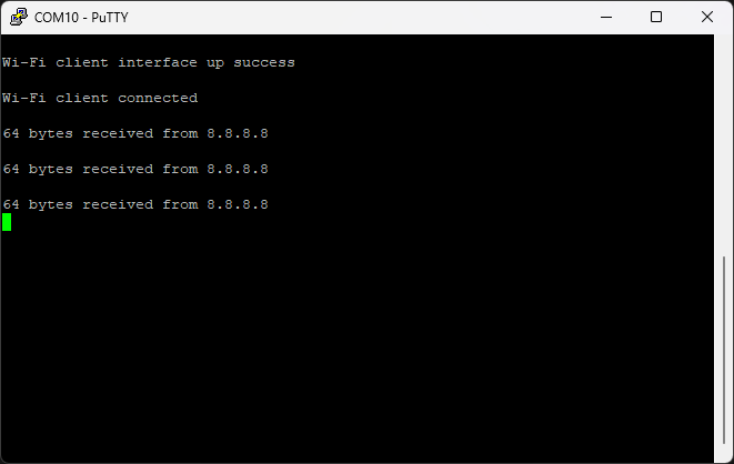
Running the Wi-Fi station_ping Example
After following the steps this far, the project is now configured to run the station_ping example to exercise the Wi-Fi radio of the Veda SL917 module.
As described above, attach the Nucleo board USB port to your workstation and identify the serial port associated with the STM32 development board (e.g., NUCLEO board). Open a serial terminal (e.g., PuTTY) to monitor the debug output printf() statements within the example project (115200 baud, 8N1).
Test out your build by clicking the Run → Debug menu option. If this is the first time you are running a project, you’ll need to click the Debugger tab and select ST-Link S/N as your debugger. If the field is empty, click Scan with your board attached via USB and it should fill in the serial number automatically. You can click OK to apply settings and attempt to program and run the firmware on your board.
The STM32CubeIDE will program the firmware, then switch to the Debug Perspective with a debug session and execution paused at HAL_Init(); in main.c. You can use the debugger perspective buttons near the top of the window to control the debug session. Press the green “Play” button  to resume/continue running the application (or type the F8 key).
Here is an example of debug output from the station_ping example, pinging a remote host over Wi-Fi: