UART stands for Universal Asynchronous Receiver-Transmitter, a widely used serial communication interface. In this article, we'll explore UART formatting, parameters, and signaling variations.
By Mike Ulanski
Published on January 15, 2026
UART stands for Universal Asynchronous Receiver-Transmitter, a widely used serial communication interface found in microcontrollers, computers, and peripheral devices. In simple terms, a UART is a hardware module (often an integrated circuit or part of a microcontroller) that converts parallel data from a CPU or data bus into a serial bit stream for transmission, and vice versa for reception . Unlike synchronous protocols (which use a shared clock), UART communication is asynchronous – there is no clock line between the two devices. Instead, both the transmitter and receiver agree on timing parameters (like baud rate) in advance and use special bits (start/stop) to frame the data . This simplicity makes UART one of the most ubiquitous device-to-device communication methods in embedded systems, requiring only two signal wires (TX for transmit, RX for receive) for full-duplex data exchange.
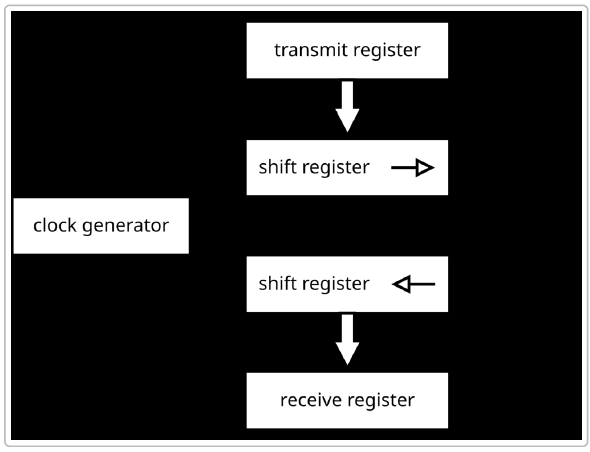
Under the hood, a UART is essentially a translator between parallel and serial data. It takes bytes of data and sends the individual bits sequentially (bit-by-bit) over a single data line . On the receiving end, another UART reassembles the bit stream back into bytes. Each UART contains components like a clock generator (to derive timing), shift registers for serial/parallel conversion, and buffers or FIFO memory for temporarily holding incoming/outgoing data . The following is an illustration of a simplified UART block diagram, showing how data moves from parallel registers through shift registers to serialize for transmission and then back to parallel form on reception .
Because UART communication does not include a shared clock, both sides must be configured with matching settings to ensure reliable data exchange . The next sections will explain how UART frames data for transmission, what parameters need to be configured, and what variations of UART signaling are commonly used (e.g. TTL, RS-232, RS-485). We will also compare UART with other serial protocols and discuss its use in modern applications like IoT and embedded systems.
UART communication is often described as asynchronous serial transmission. "Serial" means bits are sent one after another on the wire, and "asynchronous" means the timing is not governed by a shared clock but by agreed-upon signaling conventions. Instead of a clock, UART uses start bits and stop bits to delineate each data packet (frame) so that the receiver can synchronize to the sender's bit stream . When the line is idle (no data), it stays in a high voltage state (logic 1). The beginning of a transmission is signaled by a Start Bit, which is a transition from high to low (logic 0) for a duration of one bit period . This alerts the receiver that a new byte of data is starting. Following the start bit, the data bits are sent out LSB (least significant bit) first, typically 8 data bits (though 5 to 9-bit frames are possible) . An optional Parity Bit may follow, which is used for simple error checking by indicating whether the number of 1s in the data bits was even or odd . Finally, one or more Stop Bits (logic high) are sent to mark the end of the frame, allowing the line to return to the idle state . The stop bit(s) also provide a brief buffer period before the next start bit could occur.
To better understand the process, let's break down the steps of a UART transmission from sender to receiver:
This entire process happens continually as data is transmitted. If the sender has more bytes to send, it can transmit frame after frame back-to-back, as long as it ensures a stop bit interval between bytes. The receiver will continuously look for the start-bit transition from high to low to synchronize on each new frame.
Baud Rate and Synchronization: Both UARTs must be configured to use the same baud rate, which is the speed of transmission in bits per second (bps). Common standard baud rates include 9600, 19200, 38400, 57600, 115200 bps, etc., though many UARTs also support higher rates (several megabits per second) . The accuracy of the baud rate on both sides needs to be quite close – typically within about 2% for error free communication, with a tolerance up to around 5–10% maximum difference before bits start misaligning . For example, at 9600 bps each bit is ~104 microseconds long, so if one clock is significantly faster than the other, the sampling of bits will drift over a frame. UART receivers often use an oversampling technique (e.g., 16x sampling per bit) to precisely detect the middle of each bit and to tolerate small clock mismatches . As long as the baud rates are nearly the same on both ends, the start/stop framing allows the two devices to stay in sync without a shared clock line.
Error Detection: UART includes some basic error detection mechanisms. As noted, a parity bit can be enabled (configurable as even parity or odd parity) which lets the receiver detect if a single bit flipped during transmission (if the parity of the received data doesn’t match the expected even/odd count, a parity error flag is raised) . A framing error occurs if the receiver does not see a valid stop bit at the expected time – for instance, if the line stays low when it should have gone high, indicating the frame got out of sync . UART hardware typically flags framing errors so the system knows that byte may be corrupted. Another condition is a buffer overrun, which happens when a new byte arrives before the previous one was read from the receive buffer – essentially the UART’s receive FIFO or register gets overwritten because the system didn’t service it in time . Many UARTs will set an overrun error flag in this case. There is also a concept of a break condition, which is when the line is held low longer than a full frame duration with no stop bit – this is sometimes used intentionally as a signal (for example, to indicate a reset or to begin a special mode) .
Flow Control: Because UART is often used to connect devices of differing speed or with limited buffering, flow control mechanisms can be employed to prevent data loss when the receiver is not ready. There are two types: - Hardware flow control: This uses additional lines – typically RTS (Request to Send) and CTS (Clear to Send) – which are essentially handshaking signals. For example, the receiver can de-assert CTS to tell the transmitter to pause sending if its buffers are full. When ready, it asserts CTS and the transmitter resumes. This ensures no data is sent when the receiver can't handle it . - Software flow control: This is an in-band method using special characters in the data stream, usually XON/XOFF. The receiver sends an XOFF character to signal the transmitter to pause sending, and later an XON character to resume. This approach doesn't require extra wires but slightly complicates the data stream (the control bytes must be escaped or not used for other purposes) .
Not all applications use flow control, but for high-speed UART links or where a slow device might get overwhelmed, flow control is important to avoid overruns. Many UART hardware modules support automatic RTS/CTS handling.
Each UART communication link must be configured with the same frame format and timing on both the transmitting and receiving side. The key parameters that define a UART frame and link are the baud rate (bits per second), number of data bits, parity setting, and number of stop bits. If any of these settings differ between the two devices, communication will fail or result in garbled data. In practice, setting up a UART means choosing a common protocol like for example "8-N-1 9600" (which translates to 9600 baud, 8 data bits, No parity, 1 stop bit – one of the most common configurations).
Some UARTs and protocols support variations like 7 data bits with even parity (7-E-1), or 8 data bits with odd parity (8-O-1), etc., as well as either 1 or 2 stop bits. The data bits can actually range from 5 up to 9 bits long in some UART hardware (5-bit and 6-bit frames were historically used for teletype or Baudot codes, and 9-bit modes are sometimes used in multi-drop networks or special protocols). Parity can also be set to None (no parity bit at all), which is common if error detection is either not needed or handled by higher-level protocols.
For two UART devices to communicate correctly, they must share identical settings on the following parameters:
If any of the above differ, the devices will not interpret the serial data in the same way. For example, if one device sends 7-E-1 (7 data bits, even parity, 1 stop) and the other is set to 8-N-1, the extra parity bit from the first device will be seen as an eighth data bit on the second, ruining the communication. Similarly, a mismatch in baud rate means the sampling points won't line up and the bits will be mis-read. It’s the developer’s responsibility to configure both ends of a UART link with matching parameters (in embedded systems this often means setting UART control registers appropriately based on an agreed protocol or using standardized defaults for certain devices).
Modern UART hardware often includes FIFO buffers (e.g., 16-byte or larger FIFOs in PC UART chips like the 16550 family ) to allow higher baud rates without dropping data. These buffers let the CPU service the UART at a more leisurely pace by reading chunks of data at once. UART modules on microcontrollers also frequently provide interrupts or DMA support to handle data efficiently. Advanced features can include programmable baud rate generators (using divisors and fractional divisors to achieve common baud rates from various clock sources) , and various error detection flags as discussed.
Another important point is that UART by itself is a point-to-point communication; it doesn’t inherently support addressing multiple devices or bus arbitration. If you connect a UART TX line to two RX lines (multidrop), those two receivers will both receive the same data, but they cannot both talk back on a single shared TX line without interfering. There are protocols and schemes to allow a form of multi-drop (for instance, the 9-bit UART mode is sometimes used to include an address bit to identify packets, or using an external transceiver like RS-485 which allows bus sharing – more on that next), but vanilla UART is typically one transmitter to one receiver. This is in contrast to protocols like I²C which are multi-device by design. If a network of multiple devices is needed, higher-level protocols must be implemented on top of UART or different physical layers must be used.
When we talk about UART protocols, it often includes not just the basic UART framing explained above, but also the physical interface standards and line protocols that carry UART signals. The UART hardware generates the serial bit stream, but the electrical signaling can vary. The most common physical interfaces associated with UART communication are TTL-level serial, RS-232, and RS-485 (there's also RS-422, which is similar to RS-485). These can be considered variants or implementations of UART communication, each suited to different voltage levels, distances, and environments.
TTL serial refers to using UART directly at the logic levels of the microcontroller or digital system – typically 5V or 3.3V logic levels (TTL or CMOS voltage levels). In TTL serial, a logic "1" is represented by a high voltage (e.g. 3.3 or 5 volts) and "0" by low (0 volts), using the same convention as the microcontroller’s logic. The idle line is high (Vcc level) and the start bit is a transition to 0V. This is the simplest form and is used for on-board communications or short links between ICs. For example, when you connect an Arduino or Raspberry Pi to a GPS module or Bluetooth module via serial pins, they often use TTL-level UART signals. TTL serial links are only reliable over short distances (typically on the order of a few tens of centimeters to a couple of meters at most) because they are single-ended (one wire for TX referenced to a common ground) and not designed for noise immunity. Also, TTL logic levels are not standardized across different voltage domains; a 5V UART output could damage a 3.3V input unless level shifting is used. One must ensure the two devices share a common ground reference and compatible voltage levels. If not, a level shifter or adapter is needed to translate the signals.
Many debugging and programming connections on development boards are TTL UART – for instance, the 6-pin programming header on Arduino (labeled with TX, RX, GND, etc.) or the serial console on a Raspberry Pi’s GPIO header are TTL UARTs. To connect these to a PC, we use a USB-to-TTL UART adapter (these contain a UART chip like FT232R or CP2102 and a USB interface) which converts between PC USB and the board’s TTL serial . Common signal levels for TTL UART are 0 to +3.3V or 0 to +5V (and some adapters support 1.8V or 2.5V as well) – unlike RS-232, TTL serial is not inverted (logic 1 is high voltage) and uses a narrow voltage swing, so it’s only suited for short, low-noise environments .
RS-232 is a long-established standard (dating back to the 1960s) for serial communications between computers and peripheral devices. It uses UART communication at its core (asynchronous serial frames), but defines a specific electrical signaling: RS-232 signals are voltage inverted and use higher voltage levels than TTL. In RS-232, a logical "1" (idle state) is represented by a voltage between -3 V to -12 V, and a logical "0" is +3 V to +12 V . This means RS-232 requires driver circuits (level converters) to translate between the UART’s TTL logic and the RS-232 line levels. A common chip for this is the MAX232, which uses charge pumps to generate ±10V from a 5V supply.
Key characteristics of RS-232 include: - It is point-to-point only (one transmitter, one receiver). Typically labeled as a connection between a DTE (Data Terminal Equipment, e.g. a PC or terminal) and DCE (Data Communications Equipment, e.g. a modem). - Full-duplex communication is supported: RS-232 cables usually have separate transmit and receive pins, as well as other control lines. The standard DB9 connector can have many signals (TxD, RxD, RTS, CTS, DTR, DSR, etc.), though for basic communication only Tx, Rx and ground are required . - The signal levels and robustness allow it to reach distances of around 15 meters (50 feet) reliably at lower baud rates . However, it’s susceptible to noise over long cables because it’s single-ended (common ground) and uses high voltage swings that can pick up interference. Also the impedance and cable capacitance limit its speed over distance. - Speed: RS-232 can support baud rates up to around 115 kbps easily, and in some cases up to a few Mbps with short cables (Black Box notes RS-232 can go up to ~3 Mbps under ideal conditions) . Historically, standard PC serial ports ran up to 115,200 baud, though custom setups might achieve higher. At long cable lengths, the max rate drops (the original standard suggested 20 Kbps at maximum distance). - Because RS-232 uses ± voltages, it is not directly compatible with TTL logic – you must use a level translator. Also, the negative voltage for "1" and positive for "0" means the logic sense is inverted relative to TTL levels . These converters also protect the UART from high line voltages. Without conversion, connecting an RS-232 port to a TTL UART pin can damage the hardware. - RS-232 has been largely phased out of personal computers (most modern PCs no longer have a DE-9 serial port) in favor of USB, but it remains in use in many industrial machines, networking equipment (console ports), and instrumentation. USB-to-RS232 adapters are available for PC connection .
Some drawbacks of RS-232, compared to newer standards, include its large voltage swing (which can be more power-hungry and require special drivers), limited multi-drop capability (only two devices on a link), and the need for a common ground which can create grounding issues or ground loops in large systems . It’s also limited in noise immunity compared to differential methods.
RS-485 (also known as EIA-485) is a serial interface standard that, like RS-232, uses asynchronous UART communication but with a different physical layer to address some of RS-232's shortcomings. RS-485 uses differential signaling: instead of one wire and ground, it drives a pair of wires with opposite voltages. A logic "1" is represented by, say, line A > line B by at least +200 mV, and a "0" by A < B by that voltage (the actual driver swings are typically 0 to 5V differential) . The lines are typically a twisted pair, and this balanced differential mode gives RS-485 excellent noise immunity and the ability to drive signals over much longer distances.
Important features of RS-485 include: - It is typically used in a bus topology: multiple receivers (and transmitters) can share the same pair of wires. RS-485 supports up to 32 devices on the bus (32 unit loads, and with modern low-load drivers, even more nodes can be allowed). This makes it suitable for multi-drop networks (e.g., connecting many sensors or devices in a network configuration). - Half-duplex communication is the norm for RS-485: all devices share the same two-wire differential pair for both transmit and receive, so only one device should transmit at a time (others listen). This requires a simple protocol for devices to take turns (master-slave schemes or other arbitration). Full-duplex is possible but requires two pairs (one for TX, one for RX), which is essentially like having two RS-485 links for simultaneous send/receive . Many RS-485 implementations are two-wire half-duplex to save wiring. - Range: RS-485 can achieve very long distances, on the order of 1200 meters (about 4000 feet) at lower speeds . It’s commonly used in industrial environments for connecting devices across factory floors or between buildings (for instance, Modbus RTU networks, or DMX512 for stage lighting control). Even at long distance, the differential method resists noise (common-mode noise is cancelled out). - Speed: RS-485 can support high data rates – up to 10 Mbps or even 35-50 Mbps on shorter cables, and around 100 kbps at the maximum distances . This is much faster than traditional RS-232’s practical limits. In practice, many RS-485 networks run at 9600 or 19200 baud for reliability over long runs, but the capability for higher speed is there for shorter networks. - RS-485 uses voltage levels roughly in a 0 to +5V differential range, and unlike RS-232, it’s not inverted (the differential polarity carries the bit value). It often requires a 5V (or 3.3V) power supply for the transceiver chips, which interface directly to UART logic. - Because multiple transmitters share the bus in RS-485 half-duplex, the transceivers usually have a driver-enable control pin. Only the device transmitting will enable its driver (driving the line), and others put their drivers in high-impedance mode to avoid contention. This is typically managed by the UART or software (for example, in a microcontroller you might manually toggle a GPIO to enable the RS-485 driver when you send, or some UARTs have built-in support to automatically toggle the transmit enable line when data is sent).
RS-485 has become the workhorse for industrial serial communications and is used in protocols like Modbus RTU, Profibus, BACnet MSTP, and others. It’s also common in building automation, CCTV (PTZ camera control), and any scenario that needs robust serial links over long distances. In IoT and embedded contexts, RS-485 allows sensor networks or multiple microcontrollers to communicate over one pair of wires. One trade-off is that the communication is half-duplex on a single pair, so the software protocol must handle turn-taking, and collision avoidance if using a multi-master approach.
| Feature | RS-232 Serial | RS-485 Serial |
|---|---|---|
| Signaling | Single-ended (voltage referenced to ground). Logic 1 = -3V to -12V, Logic 0 = +3V to +12V (inverted logic levels). | Differential pair (A/B lines). Logic defined by voltage difference (e.g. >+200 mV = 1). Approx. +5V to -5V differential swing (non-inverted relative logic). |
| Duplex Mode | Full-duplex (separate TX and RX lines; simultaneously send and receive). | Half-duplex typical (one pair shared for TX/RX, devices take turns). Full-duplex possible with two pairs (rarely used) . |
| Maximum Devices | 1:1 connection (one transmitter, one receiver). No multi-drop without additional circuitry. | Multi-drop bus (supports up to 32 transceivers on one line by standard; more with extended driver designs). Suitable for multi-device networks . |
| Cable Wiring | Typically uses a 3-wire or multi-wire cable (Tx, Rx, GND; plus other control lines in full serial cables). Standard connectors (DB9/DB25) have many pins, though only a few are essential. | Uses a twisted pair (+ optional second pair for full-duplex). Often just 2 wires (+ ground reference). Simple two-wire bus for all nodes. |
| Distance (Max) | ~15 meters (50 feet) at nominal speeds. Practically shorter for higher baud (length affects speed). | ~1200 meters (4000 feet) at lower speeds. Very long distances achievable; at max distance, speed is limited (~100 kbps). |
| Data Rate | Up to ~115 kbps commonly; maximum around 1 Mbps to 3 Mbps in short links. Performance degrades with cable length and capacitance. | Up to 10 Mbps or more on short runs, and usable into the low Mbps over hundreds of meters. Can greatly outperform RS-232 in speed over distance. |
| Use Cases | Legacy PC COM ports, modem connections, configuration ports for networking gear, some laboratory instruments. Still seen in point-to-point console connections. | Industrial networks (Modbus, Profibus, etc.), building automation, multi-drop sensor networks, CCTV control, any environment needing rugged long-range serial links. Common in IoT for sensor/actuator buses. |
| Pros | Simple point-to-point wiring; full-duplex; widely supported historically. | Long range, high noise immunity; supports many devices on one bus; high speeds possible. |
| Cons | Limited distance and speed; only two nodes; signal inversion and level shifting required for logic devices; susceptible to noise and ground potential differences. | Requires coordination for half-duplex (more complex protocol); still slower and lower node count than modern fieldbuses; needs differential transceivers. |
Both RS-232 and RS-485 ultimately carry UART frames – the differences are in the line encoding and network topology. Often, you will see device datasheets say something like "UART interface with RS-232 levels" or "UART with RS-485 transceiver". This means the underlying data format is UART, but the hardware line driver conforms to that standard. In many cases, one can convert a UART from one standard to another using external adapter circuits (for example, an RS-232 to RS-485 converter is essentially translating the voltage scheme and possibly converting from full-duplex to half-duplex wiring).
It’s worth noting that TTL serial vs RS-232 confusion is a common pitfall: a beginner might connect a microcontroller UART TX directly to a PC’s RS-232 port not realizing the voltage mismatch. Always ensure the physical layer levels match (use level converters or the appropriate adapter).
It is useful to contrast UART with other common serial interfaces like SPI (Serial Peripheral Interface) and I²C (Inter-Integrated Circuit), which are often mentioned in the same context. All three are methods to transfer data serially, but they differ significantly in design and usage:
In summary, UART is best for simple point-to-point communication, especially between a microcontroller and a PC or a single peripheral, or for debug logs. SPI is used when speed is critical or a rigid master/slave relationship is fine (like reading data from a high-speed ADC, driving an LCD, etc.). I²C is used for sensor networks on a board where you want minimal wiring and have multiple devices. Unlike UART, both SPI and I²C require all devices to share a timing reference (clock), which generally limits them to short distances (they are meant for communication on the same PCB or between boards in close proximity – usually inches or a few feet at most). UART, with appropriate transceivers (like RS-485), can scale to much longer distances, making it suitable for off-board or cable communication in a way SPI and I²C are not.
Another difference is that UART communication is typically peer-to-peer, with no inherent master; either side can initiate transmission as long as the line is idle (though in practice, often one device is primarily the data sender and the other the receiver, or it's turn-based). I²C always has a master orchestrating communication, and SPI has a single master controlling clock. So UART gives more flexibility for two intelligent devices to talk freely (like two microcontrollers exchanging data), but you have to avoid collisions on the single shared line if both try to talk at once – usually higher-level design or protocols handle this (or using separate wires for two UARTs if full bidirectional communication is needed without contention). It’s interesting to note that UART, SPI, and I²C can complement each other in a system. For example, a design might use I²C to read several sensor chips, SPI to talk to a high-speed ADC and an SD card, and UART to send the collected data to a PC or transmit debug info.
UART has stood the test of time as a fundamental communication protocol in electronics. From early teletypewriter connections to modern IoT devices, the universal asynchronous receiver-transmitter remains a universal solution for point-to-point data transfer. Its frame format of start bits, data bits, optional parity, and stop bits has proven flexible enough to be adapted to numerous applications and standards. While more complex serial protocols and interfaces have emerged (USB, Ethernet, CAN, etc.), UART fills a niche for simple, reliable, low-overhead communication between two devices. One reason UART continues to thrive is that it operates at the data-link layer independent of the physical medium . By swapping out line drivers, the same UART module in a microcontroller can send data over short on-board links (TTL serial), long cables (RS-485 differential), or even wirelessly (via Bluetooth or other serial radio modules). This adaptability, combined with the near-universal availability of UART ports, means engineers can always find a way to get two systems talking using UART. Even as PCs phased out true serial ports, USB-to-UART bridges stepped in, underlining the persistent demand for serial connectivity .
In modern embedded and IoT development, UART often serves as the lifeline for debugging and configuration, ensuring that there’s a straightforward way to interact with a device. Many devices ship with a UART bootloader or console that can be a lifesaver when other interfaces aren’t working. And in deployed systems, protocols built on UART (like Modbus RTU, LIN, or custom serial protocols) handle tasks from industrial control to smart home device communication.
In conclusion, the UART protocol’s overview shows a technology both humble and powerful: humble in its simplicity (just shifting bits out and in, no fancy handshakes or headers required), yet powerful in its broad applicability and the depth of technology built around it. Whether you're an embedded engineer linking a sensor to a microcontroller, or an IoT developer configuring a fleet of devices, understanding UART is essential. It might not have the buzz of newer protocols, but it's the sturdy workhorse ensuring that when one device talks, another can listen – the essence of connectivity. As the famous engineering adage goes, "if it ain't broke, don't fix it" – UART isn’t broken, and it’s likely to keep enabling communications for decades to come, continuing its quiet role in the background of cutting-edge technologies.