/filters:background_color(white)/2024-12/mFlexPIFA-standalone-transparent.png)
3 Reasons to Choose Embedded Connectivity for Your Design
Wireless Inside – An Approach with Countless Benefits Wireless connectivity is increasingly an absolute requirement in new products across every industry. The applications of the...
What Every Engineer Needs to Know Before Designing In a Wi-Fi Module
Published on April 14, 2026
Some wireless module datasheets
list an M.2 form factor and call it done. What they don't tell you is that
"M.2" is not a single specification — it's a family of mechanical
form factors, keying configurations, and interface assignments that have
evolved across generations of PCIe, SATA, USB, and now Wi-Fi/Bluetooth
co-existence use cases. Getting that combination wrong costs you a board spin.
In some cases, it costs you regulatory recertification.
This post is for engineers who are past the marketing layer and need to understand exactly what the M.2 standard governs, which key configurations matter for wireless modules, how the underlying hardware interface choices affect firmware integration and antenna design, and where the practical traps live in design and procurement. It also covers how Ezurio's M.2 Wi-Fi modules implement this standard — and why the implementation details matter as much as the form factor itself.
M.2 — formally standardized as the Next Generation Form Factor (NGFF) by JEDEC under publication JESD22-B218 and maintained by the PCI-SIG in their M.2 specification document — was originally designed for SSDs and wireless cards in thin-and-light laptops. It has since migrated heavily into industrial, medical, and embedded IoT computing platforms because it offers a compact, board-mount footprint with a standardized connector ecosystem, high-speed interface options, and an RF coaxial antenna connector position that is consistent across implementations.
The adoption curve has created a real procurement and engineering risk: platform designers often spec an "M.2 slot" without fully locking the key type, interface lanes, or supported form factor dimensions. Module vendors — including many in the wireless space — produce M.2 modules that fit the mechanical footprint but require interface configurations the host platform was not designed to support. The result is a module that physically seats but doesn't enumerate, doesn't authenticate, or introduces ground plane interference with the antenna system.
Recent industry consolidation in the wireless module space has made this worse, not better. As platforms increasingly rely on M.2 for both compute and wireless co-location, the number of engineers encountering these edge cases has grown. There is no single "M.2 Wi-Fi standard" — the standard governs the connector, the keying, and the lane assignment. Everything beyond that is implementation.
It's a common occurrence in tech that standardization helps move whole industries forward. Fragmented form factors and specifications lead to OEM lock in and discourage innovation and experimentation, and open standards eliminate the distractions that keep industries from moving forward. Moving to the M.2 standard has real advantages for OEMs designing in wireless, and Ezurio's Sona modules leverage this standard to give our customers the best foot forward for futureproofing and supply chain resilience for their future designs. But it's important to understand the wide variety of M.2 options, the difference between pluggable and solder-down form factors, and the unique considerations for each.
M.2 modules are identified by a four- or five-digit code that encodes width and length in millimeters. The first two digits are width; the remaining two or three are length.
For wireless modules, traditional socketed formats such as 2230 and 3042 remain common in PC-compatible and modular embedded platforms. However, smaller solder-down M.2 form factors such as 1216 (12 × 16 mm) and 1218 (12 × 18 mm) are increasingly used in space-constrained IoT and industrial designs where connector height, cost, and vibration tolerance are critical.
| Module Code | Width | Length | Common Use Case |
|---|---|---|---|
| 1216 | 12 | 16 | Ultra-compact IoT, solder-down designs |
| 1218 | 12 | 18 | Compact embedded wireless, no connector |
| 2230 | 22 | 30 | Compact wireless, embedded platforms |
| 2242 | 22 | 42 | Budget SSDs, some wireless cards |
| 2260 | 22 | 60 | Mid-range SSDs |
| 2280 | 22 | 80 | Consumer NVMe SSDs |
| 3042 | 30 | 42 | Industrial wireless, high-component-count modules |
For our purposes, the most important M.2 form factors for discussion are 1216, 1218, and 2230. These are the form factors which serve the embedded applications we serve. The M.2 standard actually supports 12, 16, 22, and 30mm widths, as well as 16, 26, 38, 42, 80, and 110 mm lengths.
Unlike larger M.2 modules, 1216 and 1218 are LGA (land grid array) form factors that are soldered directly to the host PCB. They do not use the standard 75-pin edge connector and therefore bypass keying constraints, but require tighter coordination of PCB layout, assembly, and rework processes.
Note: This keying model applies only to connectorized M.2 modules (e.g., 2230, 3042). Solder-down M.2 form factors such as 1216 and 1218 do not use keying, as they interface through direct pad connections on the PCB.
This is where most documentation fails engineers. M.2 defines multiple "key" configurations — physical notches in the edge connector that prevent a module from seating in an incompatible slot. Each key type also maps to a specific set of interface signals on the 75-pin edge connector. (While the M.2 specification provides 75 pins, in practice pluggable forms us 67 pins and set aside some of the extra pin space for key notches to prevent the card from being inserted incorrectly).
The E-key is the configuration used for wireless cards. It exposes PCIe x2, USB 2.0, I2C, and a dedicated CNVi (Connectivity Integration) interface originally developed by Intel for its own chipsets. It also includes UART lines that some wireless module vendors use for AT command interfaces when PCIe is unnecessary overhead.
The A-key overlaps mechanically with E-key modules — an A-key module can seat in an E-key slot. This is intentional and documented in the PCI-SIG M.2 specification (revision 1.0, Section 3.3), which defines the A+E keying configuration used by most modern wireless M.2 cards. The consequence is that an A+E keyed module will fit in either an A-key or E-key slot, but the host's interface routing determines which signals are actually functional.
M-key and B-key are the configurations used for NVMe and SATA SSDs, respectively. Engineers designing wireless modules into platforms that may also host storage devices need to verify that the host board's M.2 slots are dedicated E-key slots, not multi-purpose B+M slots that happen to accept A+E keyed cards mechanically but don't route the USB or PCIe lanes the wireless module expects.
For 1216 and 1218 modules, interface signals (PCIe, USB, UART, SDIO, etc.) are directly routed to LGA pads, eliminating ambiguity around slot configuration but increasing the importance of schematic accuracy and layout discipline. There is no abstraction layer provided by a connector — integration errors manifest at the PCB level rather than at module insertion.
The E-key footprint does not mandate a specific logical interface — it exposes several. Which interface a wireless module uses depends on the module's silicon and firmware architecture:
The practical implication: specifying an M.2 module without specifying the host interface type is incomplete. An E-key slot on an i.MX8 carrier board routed for USB will not bring up a PCIe-native Wi-Fi module, regardless of how well the module is keyed and seated.
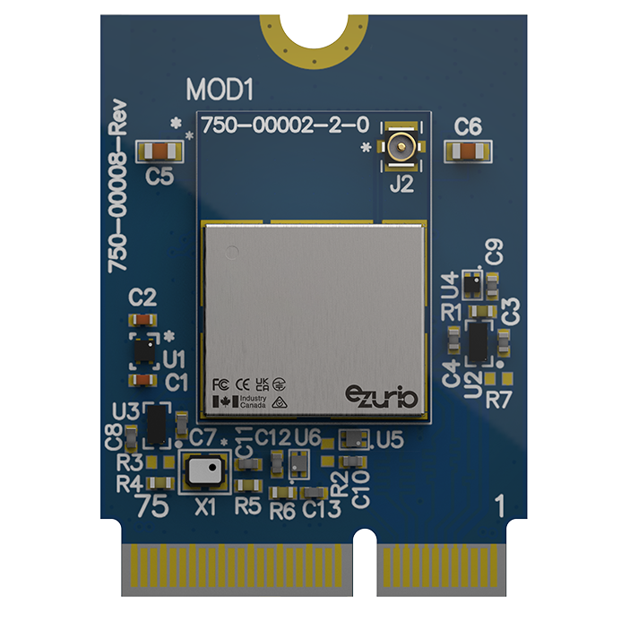
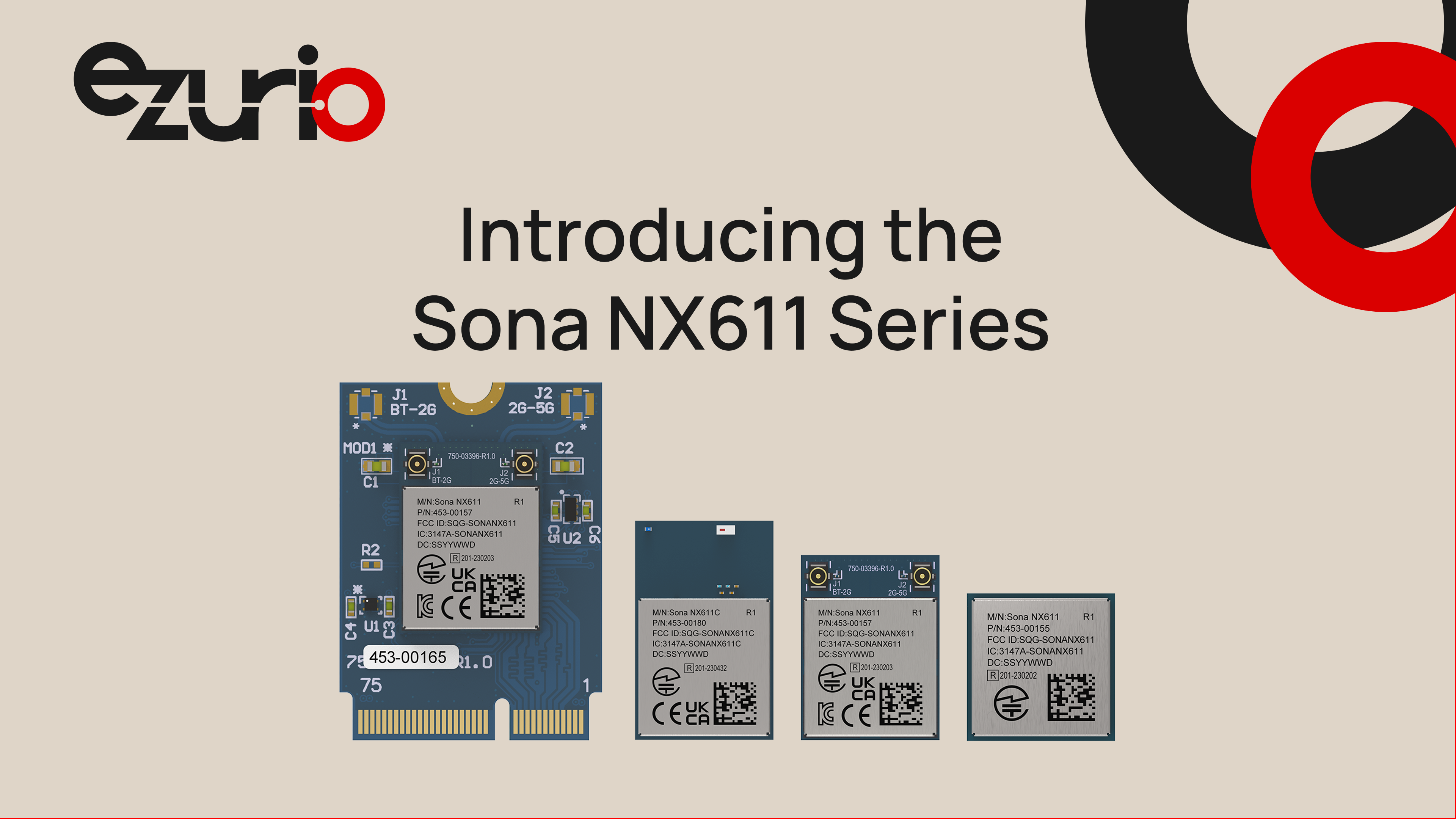
Pictured here is an example of multiple M.2 form factors within our Sona NX611 product family. From left to right, the family includes M.2 2230 Key E, M.2 1218 SMT, and M2 1216 SMT form factors (as well as an addition SiP package, which is not an M.2 standard module).
The M.2 specification defines the mechanical and electrical interface. What it doesn't define is everything that determines whether a wireless module will work reliably in a production deployment: the RF chain, the antenna connector placement, the coexistence logic, the power sequencing behavior, and the certification status.
Ezurio's M.2 Wi-Fi modules generally come in three physical sizes: 1216, 1218, and 2230. Of these, only the M.2 2230 offerings are a pluggable Key-E type. All are designed with the antenna connector at the module edge (in the 2230's case, opposite the M.2 edge connector) - a consistent physical layout that simplifies antenna routing in host enclosures. The U.FL or MHF4 coaxial connectors used on M.2 modules carry a 50-ohm impedance requirement. Violating this — through a poorly matched pigtail cable, a coaxial trace with incorrect ground clearance, or an antenna with significant return loss at the operating frequency — directly degrades link budget.
Ezurio's RF reference designs include specific antenna placement guidance and ground plane keepout requirements that are not captured in the M.2 specification itself. These documents are part of the module integration package, not afterthoughts — they reflect the measured antenna interaction behavior of the module in a representative host PCB environment. This is one of the ways that Ezurio provides our customers greater consideration and integration assistance over what might be considered "good enough" by a competitor.
Most enterprise-grade M.2 wireless modules implement both Wi-Fi and Bluetooth on a single module, sharing a common antenna or using two separate RF paths. The M.2 pinout exposes a COEX interface — a group of signals including BT_PRIORITY, WLAN_ACTIVE, and BT_ACTIVE — that allows the Wi-Fi and Bluetooth subsystems to negotiate shared medium access in the 2.4 GHz band.
This coexistence interface is frequently left unconnected on embedded platforms that don't implement BT, which is generally harmless. However, platforms that implement both Wi-Fi and BT through independent devices — module-based Wi-Fi plus a separate BT UART module — without connecting the COEX lines will experience interference that manifests as erratic throughput degradation and inconsistent BT connection quality under simultaneous load. Ezurio's modules implement software-based coexistence management that reduces (but does not completely eliminate) the impact of unconnected hardware COEX lines.
M.2 wireless modules expose multiple power rails: 3.3V primary supply, and in some implementations a separate 1.8V I/O rail. The PCI-SIG M.2 specification defines power sequencing requirements for compute modules, but the sequencing behavior for wireless modules is less rigidly standardized and varies between silicon vendors. Ezurio's module datasheets specify ramp-rate requirements and enable line timing — exceeding the ramp rate can cause the module's internal LDOs to brown out before the module fully initializes, resulting in failures that appear intermittently and are difficult to reproduce in lab conditions.
Common Misconfiguration Warning: The most common power-related issue in M.2 wireless integration is a host platform that applies 3.3V to the M.2 connector before the enable signal is asserted, then deasserts the enable signal without removing power during sleep modes. Some module firmware implementations treat this as a reset signal; others do not. Verify your module's enable line behavior against the datasheet before finalizing power sequencing logic.
While electrically aligned with the broader M.2 ecosystem, 1216 and 1218 introduce different integration constraints:
Assembly Process
Reliability
Thermal Design
RF Layout Sensitivity
No Mechanical Abstraction
The following steps reflect the design sequence that avoids the most common integration failures. Work through these in order before committing board layout.

M.2 wireless modules sold into North American and European markets carry modular transmitter certifications under FCC Part 15 Subpart C (for Wi-Fi) and Part 15 Subpart B (for incidental emissions). The FCC's modular approval framework — defined in KDB Publication 996369 — specifies the conditions under which a module's grant of authorization can be used in a host platform without requiring the host to undergo full RF testing.
The critical provision is antenna restriction: a modular transmitter's FCC grant covers specific antenna types and maximum gain levels. Substituting a higher-gain antenna, using a cable length not covered by the module's test configuration, or locating the antenna in a way that changes the radiation pattern relative to the module can void the modular transmitter's applicability and require host-level authorization. This is not a theoretical risk — it comes up in every FCC consultation involving a new enclosure design.
Under the EU Radio Equipment Directive (RED, Directive 2014/53/EU) and its UK equivalent post-Brexit, similar provisions apply. ETSI standard EN 300 328 v2.2.2 defines the conformance testing methodology for 2.4 GHz WLAN devices; EN 301 893 v2.1.1 covers 5 GHz. Ezurio's M.2 modules carry CE marking under these standards, but the end-product manufacturer retains responsibility for ensuring that the installation conditions remain within the tested configuration.
The EU Cyber Resilience Act (CRA), which entered into force in December 2024 and applies to products with digital elements placed on the EU market, adds a software security dimension that extends beyond RF compliance. Wireless modules that implement network interfaces are within scope of the CRA's essential cybersecurity requirements, which include vulnerability handling obligations and security-by-default configuration requirements. For M.2 Wi-Fi modules specifically, this means the host platform manufacturer must be able to demonstrate that the module's firmware can be updated and that the module ships in a secure default configuration — both capabilities that Ezurio supports.
Follow the latest updates to RED Cyber and the EU Cyber Resilience Act in our Ezurio Security Center.
M.2 is a form factor family, not a single specification — and understanding the distinction between mechanical compatibility and functional compatibility is the difference between a clean first board spin and a costly re-design. Emerging solder-down M.2 form factors such as 1216 and 1218 extend the standard into ultra-compact and high-reliability applications, but shift integration complexity from connector compatibility to PCB design, assembly, and RF layout precision. E-key modules expose multiple interface options (PCIe, USB, UART), and which of those interfaces is actually routed on a given host platform determines which modules will work. Antenna system design, coexistence wiring, and power sequencing requirements exist outside the M.2 specification entirely and must be sourced from the module vendor's reference design documentation.
Ezurio's M.2 Wi-Fi modules are engineered for the full design context: certified RF architectures, documented power sequencing parameters, and coexistence logic that reflects the realities of mixed wireless environments. The M.2 footprint is the starting point for integration — the hardware and firmware that Ezurio delivers within that footprint is what determines whether the module performs to specification in a deployed product.
To discuss M.2 wireless module integration for your platform — including interface selection, antenna design review, or certification questions — contact Ezurio's engineering team at ezurio.com.
Wireless Inside – An Approach with Countless Benefits Wireless connectivity is increasingly an absolute requirement in new products across every industry. The applications of the...
/filters:background_color(white)/2024-10/FlexMIMO6E--Crop.png)
Akron, Ohio – December 8, 2021 – Next-generation Wi-Fi 6E provides a foundation for faster, better-performing, lower latency wireless networks at a time when the demands on Wi-Fi networks are...
/filters:background_color(white)/2019-06/custom-antenna-exploded_0.png)
Just about everything is going wireless these days, as the Internet of Things continues to gain steam. This has been the trend for some time in consumer electronics, like lighting that you can...
/filters:background_color(white)/2025-03/whitepaper-5-basics-of-rf-design.jpg)
If it's time to go wireless, don't forget the basics of RF Design. You may be excited about your new wireless project: innovative design, environmentally friendly, consumer demand, and the list could...
/filters:background_color(white)/2018-11/Monitor-Graphic-WirelessTechnology.png)
The IoT encompasses a wide variety of wireless technologies across an endless array of applications. From the millions of smartphones and tablets to machines, buildings, and countless other products...