/filters:background_color(white)/2025-03/60_2230C_straight.png)
/filters:background_color(white)/s3fs-public/2018-10/60_SiP_straight.png)
Introduction
This guide covers tutorials for specific applications with the Sterling 60 Series modules.
More documentation, ordering information, and resources related to the Sterling 60 Series modules can be found on our website:
https://www.ezurio.com/wireless-modules/wifi-modules-bluetooth/60-sipt-bluetooth-and-wifi-module
Sterling-60 on Ubuntu manually installing backports and firmware
This tutorial shows how to install drivers and firmware for a Sterling 60 module on a Ubuntu PC.
Required
- Ubuntu PC
- Any variant of the Sterling 60 that will interface to the PC
Setup
To install drivers and firmware for a Sterling 60 on Ubuntu, first check the kernel version of Ubuntu is compatible with the Sterling 60 driver. Check by going to the Sterling 60 release github and read the release notes CS-RN-ST60-laird-\<version>.pdf.
Sterling 60 GitHub: https://github.com/Ezurio/Sterling-60-Release-Packages/releases
Depending on the version of Ubuntu the kernel may need downgraded.
Software
Update system and install tools:
# ensure your system is up to date
sudo apt update
sudo apt upgrade

# install software tools needed
sudo apt install make bison flex
Note: ensure any new kernel installed by updating is compatible with the Sterling 60 driver.
Hardware
This tutorial assumes hardware is interfaced to the PC correctly. Any Sterling 60 DVKs with USB support work well due to the ease of the USB interface.
The hardware used will determine the firmware used in the next section.
Install
Backports and Firmware
Download backports and the firmware that is specific to the Sterling 60 hardware to be used.
https://github.com/Ezurio/Sterling-60-Release-Packages/releases
Backports file is labeled: backports-laird-\<version>.tar.bz2
Firmware file will be based on hardware type used. For example a USB Wifi and USB Bluetooth variant will use file labeled: laird-sterling60-firmware-usb-usb-\<version>.tar.bz2.
# Extract firmware
sudo tar xvf laird-sterling60-firmware-usb-usb-<version>.tar.bz2 -C /

# Extract driver
tar xvf backports-laird-<version>.tar.bz2

cd laird-backport-<version>

make defconfig-sterling60

make

sudo make install
Blacklist
To prevent the Marvell driver from loading and interfering with the Sterling 60, black list the following by editing /etc/modprobe.d/blacklist.conf and adding the following lines:
$ sudo iv /etc/modprobe.d/blacklist.conf

# Prevent the Marvell driver from loading for the Laird ST60 module
blacklist mwifiex_pcie
blacklist mwifiex_usb
blacklist mwifiex_sdio
Reboot
Check dmesg for backports and firmware loading.
root@imx8mpevk:~# dmesg | grep -e backport -e "ieee80211 " -e Laird
[    5.529086] Loading modules backported from Summit Linux version LRD-REL-8.6.0.12-0-gd89840b36573
[    5.541965] Backport generated by backports.git v8.6.0.12
[    5.779436] <<Ezurio 60 Series Wireless Network Driver version 8.6.0.12-P39-20190123>>
[    5.810138] ieee80211 phy0: card->iobase0 = 00000000170530df
[    5.810157] ieee80211 phy0: card->iobase1 = 00000000735a0c32
[    5.812962] ieee80211 phy0: priv->pcmd_buf = 000000005f25e08f  priv->pphys_cmd_buf = 00000000ebdb9fc9
[    5.812971] ieee80211 phy0: mwl_tx_init() called: ctype=3
[    5.824326] ieee80211 phy0: TX ring: allocating 640 bytes
[    5.835121] ieee80211 phy0: TX ring: - base: 0000000077ddae7e, pbase: 0x0:c4001000,len: 280
[    5.915996] ieee80211 phy0: lrdmwl: found firmware image <lrdmwl/88W8997_pcie.bin>
[    5.946685] ieee80211 phy0: Starting fw download
[    6.757759] ieee80211 phy0: FwSize = 367340 downloaded Size = 367340
[    8.876178] ieee80211 phy0: fw download complete
[    8.888190] ieee80211 phy0: lrdmwl_pcie: pci_enable_msi failed -22
[    8.897883] ieee80211 phy0: OTP data len = 0
[    8.902719] ieee80211 phy0: Adjusting combo 0's number of supported interfaces to 2
[    8.916466] ieee80211 phy0: mwl_reg_notifier set=0 core 00
[    8.917813] ieee80211 phy0: Sending regulatory hint for 00
[    8.917871] ieee80211 phy0: mwl_reg_notifier set=1 driver 00
[    8.917889] ieee80211 phy0: Radio Type ST60 (0x0)
[    8.940422] ieee80211 phy0: Num mac 2 : OTP Version (2)
[    8.958206] ieee80211 phy0: Firmware version: 5.4.41.5
[    8.968199] ieee80211 phy0: Firmware OTP region: ff, country: 00
[    8.974259] ieee80211 phy0: Deep Sleep is disabled
[    8.979114] ieee80211 phy0: 2G enabled, 5G enabled
[    8.983955] ieee80211 phy0: 2 TX antennas, 2 RX antennas. (00000003)/(00000003)
[    9.022264] ieee80211 phy0: WMM Turbo=1
[   13.684830] ieee80211 phy0: mwl_reg_notifier set=1 country element US
Check WiFi
$ iw dev
phy#1
    Interface wlxc0ee40503358
        ifindex 3
        wdev 0x1
        addr c0:ee:40:50:33:58
        type managed
        txpower 0.00 dBm
Check Bluetooth
$ bluetoothctl
[NEW] Controller C0:EE:40:50:33:5B nuc [default]
Agent registered
[bluetooth]# power on
Changing power on succeeded
[bluetooth]# scan on
Discovery started
[CHG] Controller C0:EE:40:50:33:5B Discovering: yes
[NEW] Device 47:FE:1A:4A:AE:D3 47-FE-1A-4A-AE-D3
[NEW] Device 84:2A:FD:29:6F:FB 84-2A-FD-29-6F-FB
[NEW] Device 49:12:50:98:64:30 49-12-50-98-64-30
[NEW] Device 6A:20:51:3E:E6:37 6A-20-51-3E-E6-37
[NEW] Device 7E:97:4C:AC:BA:8A 7E-97-4C-AC-BA-8A
[NEW] Device 7F:2C:8C:7D:A2:64 7F-2C-8C-7D-A2-64
Kernel Lockdown
If the kernel module fails to load and the following "kernel_lockdown.7" shows up in dmesg then the kernel is in lockdown and easiest way around this is to disable secure boot in the PC BIOS.
[  839.299271] usb 1-4: new high-speed USB device number 15 using xhci_hcd
[  839.448101] usb 1-4: New USB device found, idVendor=1286, idProduct=2052, bcdDevice=40.00
[  839.448108] usb 1-4: New USB device strings: Mfr=1, Product=2, SerialNumber=3
[  839.448113] usb 1-4: Product: Marvell Wireless Device
[  839.448116] usb 1-4: Manufacturer: Marvell
[  839.448120] usb 1-4: SerialNumber: 0000000000000000
[  839.460273] Lockdown: systemd-udevd: unsigned module loading is restricted; see man kernel_lockdown.7
For more info see: https://man7.org/linux/man-pages/man7/kernel_lockdown.7.html https://wiki.debian.org/SecureBoot#Secure_Boot_limitations
Sterling-60 DVK-60-SIPT using USB-USB on Ubuntu
This tutorial shows how to get the DVK-60-SIPT working on a PC with Ubuntu 18.04.
Required
- Linux PC running Ubuntu 18.04 using a kernel between 3.2 to 5.4
- DVK-60-SIPT
This tutorial uses Sterling 60 Release 8.6.0.12 which supports Linux kernels 3.2 to 5.4. As new releases are available new kernels will be supported. To understand which kernel is supported by the Sterling 60 Release check the release notes on GitHub.
Setup
The setup for the DVK will use the USB/USB mode meaning the WiFi will interface with USB and Bluetooth will interface with USB. The DVK allows for other interface modes but this tutorial only covers USB/USB.
-
Hardware
-
Set switches (SW7, SW6, SW5) for WLAN and BT to use USB/USB mode
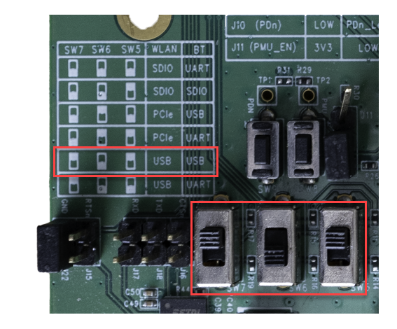
-
Set SW1 to 5V, connect 12V DC to the barrel connector, and USB cable from PC to connection USB1
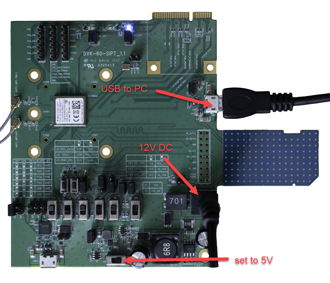
-
-
Software
-
Update system and install tools:
# ensure system is up to date sudo apt update sudo apt upgrade # install software tools needed sudo apt install make bison flex -
Note after upgrading the system it's good practice to reboot and then ensure the kernel didn't get upgraded past what is supported by the Sterling 60 Release.
-
Install
# Download backports
wget https://github.com/Ezurio/Sterling-60-Release-Packages/releases/download/LRD-REL-8.6.0.12/backports-laird-8.6.0.12.tar.bz2

# Download firmware (USB/USB specific)
wget https://github.com/Ezurio/Sterling-60-Release-Packages/releases/download/LRD-REL-8.6.0.12/laird-sterling60-firmware-usb-usb-8.6.0.12.tar.bz2

# Extract the firmware
sudo tar xvf laird-sterling60-firmware-usb-usb-8.6.0.12.tar.bz2 -C /

# Extract backports
tar xvf backports-laird-8.6.0.12.tar.bz2

cd laird-backport-8.6.0.12

# Set the config to use Sterling60
make defconfig-sterling60

# Compile the modules
make -j4

# Install modules
sudo make install
Reboot
Check dmesg for backports and firmware loading
# The usb port will vary depending on PC and USB port used

$ dmesg | grep -e 'ieee80211 ' -e 'usb 1-2' -e 'backport'
[    1.712218] usb 1-2: new high-speed USB device number 2 using xhci_hcd
[    1.866891] usb 1-2: New USB device found, idVendor=1286, idProduct=2052, bcdDevice=40.00
[    1.866894] usb 1-2: New USB device strings: Mfr=1, Product=2, SerialNumber=3
[    1.866895] usb 1-2: Product: Marvell Wireless Device
[    1.866896] usb 1-2: Manufacturer: Marvell
[    1.866897] usb 1-2: SerialNumber: 0000000000000000
[    2.946340] Loading modules backported from Summit Linux version LRD-REL-8.6.0.12-0-gd89840b36573
[    2.946340] Backport generated by backports.git v8.6.0.12
[    3.075882] ieee80211 phy0: priv->pcmd_buf = 00000000d778d804
[    3.078388] ieee80211 phy0: lrdmwl: found firmware image <lrdmwl/88W8997_usb.bin>
[    3.078482] ieee80211 phy0: start to download FW...
[    3.358464] ieee80211 phy0: info: FW download over, size 378808 bytes, ret 0
[    3.358466] ieee80211 phy0: Firmware download complete, port will reset with new interface...
[    4.701357] usb 1-2: USB disconnect, device number 2
[    5.016097] usb 1-2: new high-speed USB device number 4 using xhci_hcd
[    5.174286] usb 1-2: New USB device found, idVendor=1286, idProduct=204e, bcdDevice=32.01
[    5.174288] usb 1-2: New USB device strings: Mfr=1, Product=2, SerialNumber=3
[    5.174289] usb 1-2: Product: Bluetooth and Wireless LAN Composite Device
[    5.174289] usb 1-2: Manufacturer: Marvell
[    5.174290] usb 1-2: SerialNumber: 0000000000000000
[    5.180423] ieee80211 phy1: priv->pcmd_buf = 000000001db83880
[    5.180562] ieee80211 phy1: lrdmwl: found firmware image <lrdmwl/88W8997_usb.bin>
[    5.180563] ieee80211 phy1: Skipping FW download, continuing with initialization...
[    5.192178] ieee80211 phy1: OTP data len = 0
[    5.194165] ieee80211 phy1: Adjusting combo 0's number of supported interfaces to 2
[    5.194205] ieee80211 phy1: mwl_reg_notifier set=0 core 00
[    5.194629] ieee80211 phy1: Sending regulatory hint for US
[    5.194631] ieee80211 phy1: Radio Type ST60 (0x0)
[    5.194632] ieee80211 phy1: Num mac 2 : OTP Version (1)
[    5.194634] ieee80211 phy1: Firmware version: 5.6.41.5
[    5.194634] ieee80211 phy1: Firmware OTP region: 10, country: US
[    5.194635] ieee80211 phy1: Deep Sleep is disabled
[    5.194636] ieee80211 phy1: 2G enabled, 5G enabled
[    5.194637] ieee80211 phy1: 2 TX antennas, 2 RX antennas. (00000003)/(00000003)
[    5.194782] usb 1-2: Direct firmware load for lrdmwl/regpwr.db failed with error -2
[    5.194784] ieee80211 phy1: /lib/firmware/lrdmwl/regpwr.db not found.
[    5.194785] ieee80211 phy1: Sending regulatory hint for US
[    5.194793] ieee80211 phy1: mwl_reg_notifier set=1 driver US
[    5.194802] ieee80211 phy1: mwl_reg_notifier set=1 driver US
[    5.201755] usb 1-2 wlxc0ee40503358: renamed from wlan0
[    5.276369] ieee80211 phy1: WMM Turbo=1
[    8.280411] ieee80211 phy1: mwl_reg_notifier set=1 country element US
Check WiFi
$ iw dev
phy#1
    Interface wlxc0ee40503358
        ifindex 3
        wdev 0x1
        addr c0:ee:40:50:33:58
        type managed
        txpower 0.00 dBm
Check Bluetooth
$ bluetoothctl
[NEW] Controller C0:EE:40:50:33:5B nuc [default]
Agent registered
[bluetooth]# power on
Changing power on succeeded
[bluetooth]# scan on
Discovery started
[CHG] Controller C0:EE:40:50:33:5B Discovering: yes
[NEW] Device 47:FE:1A:4A:AE:D3 47-FE-1A-4A-AE-D3
[NEW] Device 84:2A:FD:29:6F:FB 84-2A-FD-29-6F-FB
[NEW] Device 49:12:50:98:64:30 49-12-50-98-64-30
[NEW] Device 6A:20:51:3E:E6:37 6A-20-51-3E-E6-37
[NEW] Device 7E:97:4C:AC:BA:8A 7E-97-4C-AC-BA-8A
[NEW] Device 7F:2C:8C:7D:A2:64 7F-2C-8C-7D-A2-64
Kernel Lockdown
If the kernel module fails to load and the following shows up in dmesg then the kernel is in lockdown and easiest way around this is to disable secure boot in the PC BIOS.
[  839.299271] usb 1-4: new high-speed USB device number 15 using xhci_hcd
[  839.448101] usb 1-4: New USB device found, idVendor=1286, idProduct=2052, bcdDevice=40.00
[  839.448108] usb 1-4: New USB device strings: Mfr=1, Product=2, SerialNumber=3
[  839.448113] usb 1-4: Product: Marvell Wireless Device
[  839.448116] usb 1-4: Manufacturer: Marvell
[  839.448120] usb 1-4: SerialNumber: 0000000000000000
[  839.460273] Lockdown: systemd-udevd: unsigned module loading is restricted; see man kernel_lockdown.7
For more info see: https://man7.org/linux/man-pages/man7/kernel_lockdown.7.html https://wiki.debian.org/SecureBoot#Secure_Boot_limitations
References
Sterling-60 2230C-P on i.MX 8M Plus using Yocto
This tutorial shows how to get the ST60-2230C-P m.2 board working on the i.MX 8M Plus board using Yocto.
Required Items
- ST60-2230C-P
- i.MX 8M Plus EVK
- Linux PC host machine capable of building Yocto and has a Yocto build environment already setup. For help getting the build environment setup review NXP's i.MX Yocto Project User's Guide.
Setup
-
Set the i.MX 8M Plus board to boot off SD Card
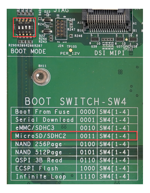
-
Install the ST-2230C-P on the i.MX 8M Plus
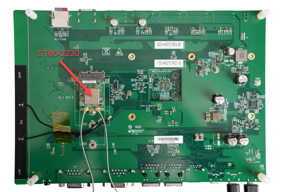
-
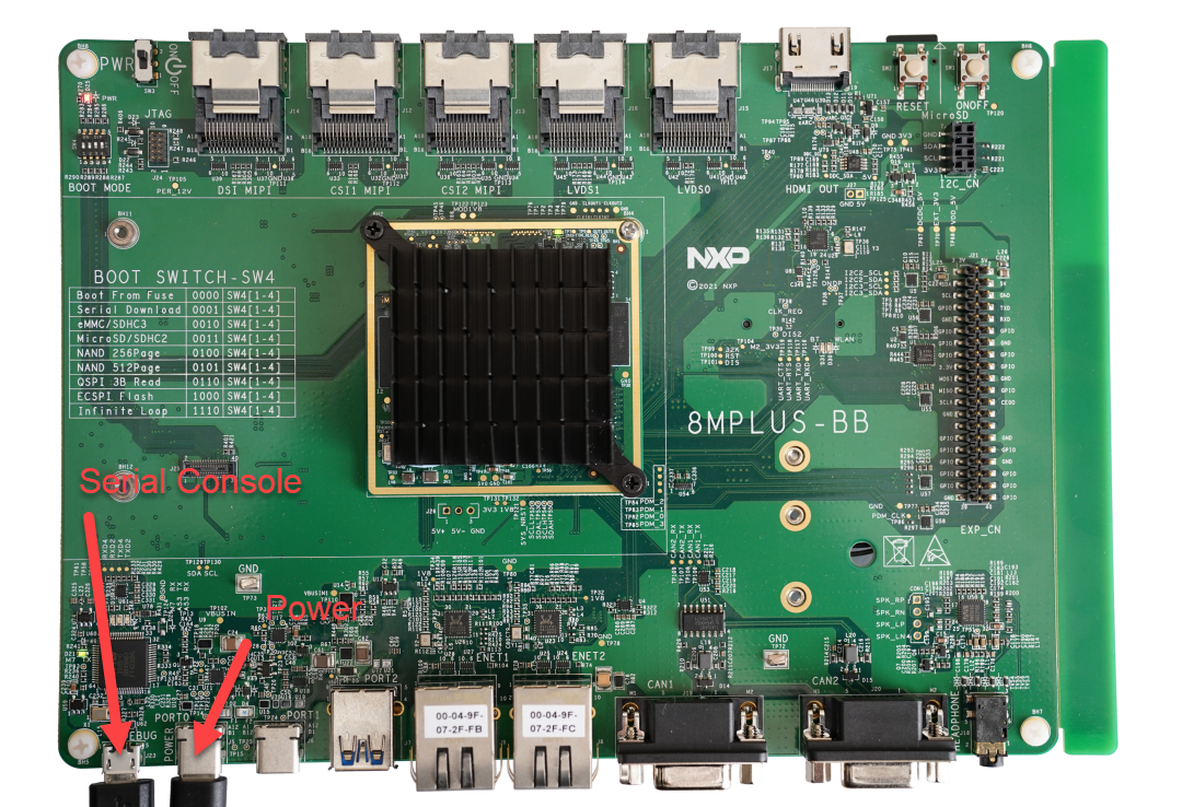
Power and serial console locations on i.MX 8M Plus EVK
Select a release
Find the latest Yocto Kirkstone release here: https://source.codeaurora.org/external/imx/imx-manifest/log/?h=imx-linux-kirkstone. At the time of this writing: imx-5.15.32-2.0.0.xml.
mkdir ~/projects/imx8mp-st60-2230c-p
cd ~/projects/imx8mp-st60-2230c-p
repo init -u https://source.codeaurora.org/external/imx/imx-manifest -b imx-linux-kirkstone -m imx-5.15.32-2.0.0.xml

repo sync
Setup Build configuration
DISTRO=fsl-imx-wayland MACHINE=imx8mpevk source imx-setup-release.sh -b build-imx8-st60-2230c-pTo re-source this directory later use the following:
. setup-environment build-imx8-st60-2230c-pSetup the Yocto Meta Layer
cd ../sources

#clone the Laird meta layer for yocto
git clone https://github.com/Ezurio/meta-summit-radio

cd meta-summit-radio/meta-summit-radio/recipes-packages/images

Note: for Yocto projects 3.3 (Hardknott) and earlier you would enter this command:
cd meta-summit-radio/meta-summit-radio-pre-3.4/recipes-packages/images

#copy the bitbake recipe example
cp sample-image-st60.bb my-st60-2230c-p.bb
Edit the bitbake recipe my-st60-2230c-p.bb
- change sterling60-firmware-sdio-sdio to sterling60-firmware-pcie-uart
IMAGE_INSTALL += "\
        iproute2 \
        rng-tools \
        ca-certificates \
        tzdata \
        alsa-utils \
        htop \
        ethtool \
        iperf3 \
        tcpdump \
        iw \
        kernel-module-st60-backports-summit \
        sterling60-firmware-pcie-uart \
        sterling-supplicant-st60 \
        summit-networkmanager-st60 \
        summit-networkmanager-st60-nmcli \
        "
Go back to the project folder
cd ~/projects/imx8mp-st60-2230c-pEdit conf/bblayers.conf
- add the meta-summit-radio layer to the bblayers.conf
BBLAYERS += "${BSPDIR}/sources/meta-summit-radio/meta-summit-radio"

Note: for Yocto projects 3.3 (Hardknott) and earlier you would enter this:
BBLAYERS += "${BSPDIR}/sources/meta-summit-radio/meta-summit-radio-pre-3.4"
Edit the conf/local.conf
- add the wpa-supplicant preferred provider, BBMASK, and wireless-regdb
PREFERRED_PROVIDER_wpa-supplicant = "sterling-supplicant"
PREFERRED_PROVIDER_wpa-supplicant-cli = "sterling-supplicant"
PREFERRED_PROVIDER_wpa-supplicant-passphrase = "sterling-supplicant"

BBMASK += " \
    meta-summit-radio/meta-summit-radio/recipes-packages/openssl \
    meta-summit-radio/meta-summit-radio/recipes-packages/.*/.*openssl10.* \
    "

PREFERRED_RPROVIDER_wireless-regdb-static = "sterling60-firmware-pcie-uart"

Note: for Yocto projects 3.3 (Hardknott) and earlier you would enter this:
PREFERRED_PROVIDER_wpa-supplicant = "sterling-supplicant"
PREFERRED_PROVIDER_wpa-supplicant-cli = "sterling-supplicant"
PREFERRED_PROVIDER_wpa-supplicant-passphrase = "sterling-supplicant"

BBMASK += " \
    meta-laird-cp/meta-summit-radio-pre-3.4/recipes-packages/openssl \
    meta-laird-cp/meta-summit-radio-pre-3.4/recipes-packages/.*/.*openssl10.* \
    "

PREFERRED_RPROVIDER_wireless-regdb-static = "sterling60-firmware-pcie-uart"
Note: the PREFERRED_RPROVIDER_wireless-regdb-static needs to be set to the firmware version used.
Configure the kernel
bitbake -c menuconfig virtual/kernelOnce in the Linux kernel menuconfig:
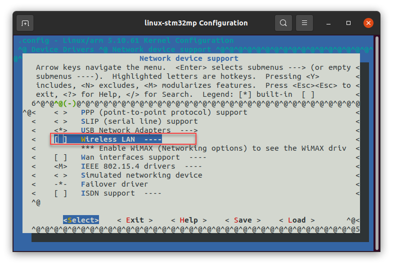
-
deselect Device Drivers -> Network device support -> Wireless LAN
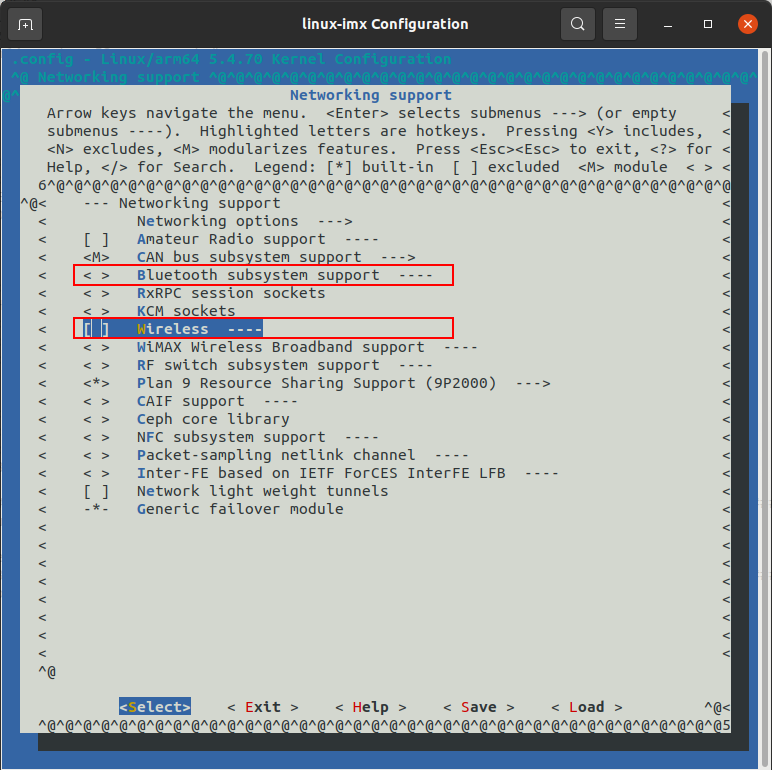
-
deselect Networking support -> Bluetooth subsystem support
-
deselect Networking support -> Wireless
Building the image
bitbake my-st60-2230c-pFlash image to SD Card
There are a couple ways to do flash the SD card image by far the easiest is to use balenaEtcher which works on Windows, Linux, and MacOS.
The SD card image will end up tmp/deploy/images/imx8mpevk/
travis@travis:~/projects/build-imx8-st60-2230c-p/tmp/deploy/images/imx8mpevk

$ ll my-st60-2230c-p*
-rw-rw-r-- 2 travis travis     3673 Sep 10 13:23 my-st60-2230c-p.env
-rw-r--r-- 2 travis travis    50291 Sep 10 13:23 my-st60-2230c-p-imx8mpevk-20210910165812.rootfs.manifest
-rw-r--r-- 2 travis travis 70295031 Sep 10 13:23 my-st60-2230c-p-imx8mpevk-20210910165812.rootfs.tar.bz2
-rw-r--r-- 2 travis travis     4142 Sep 10 13:23 my-st60-2230c-p-imx8mpevk-20210910165812.rootfs.wic.bmap
-rw-r--r-- 2 travis travis 80963806 Sep 10 13:23 my-st60-2230c-p-imx8mpevk-20210910165812.rootfs.wic.bz2
-rw-r--r-- 2 travis travis   580282 Sep 10 13:23 my-st60-2230c-p-imx8mpevk-20210910165812.testdata.json
lrwxrwxrwx 2 travis travis       56 Sep 10 13:23 my-st60-2230c-p-imx8mpevk.manifest -> my-st60-2230c-p-imx8mpevk-20210910165812.rootfs.manifest
lrwxrwxrwx 2 travis travis       55 Sep 10 13:23 my-st60-2230c-p-imx8mpevk.tar.bz2 -> my-st60-2230c-p-imx8mpevk-20210910165812.rootfs.tar.bz2
lrwxrwxrwx 2 travis travis       54 Sep 10 13:23 my-st60-2230c-p-imx8mpevk.testdata.json -> my-st60-2230c-p-imx8mpevk-20210910165812.testdata.json
lrwxrwxrwx 2 travis travis       56 Sep 10 13:23 my-st60-2230c-p-imx8mpevk.wic.bmap -> my-st60-2230c-p-imx8mpevk-20210910165812.rootfs.wic.bmap
lrwxrwxrwx 2 travis travis       55 Sep 10 13:23 my-st60-2230c-p-imx8mpevk.wic.bz2 -> my-st60-2230c-p-imx8mpevk-20210910165812.rootfs.wic.bz2
-rw-rw-r-- 2 travis travis      961 Sep 10 13:23 my-st60-2230c-p-imx-imx-boot-bootpart.wks
Flash the file ending in wic.bz2 to a microSD card. Once the flashing is done and ejected from the PC then install the microSD card into the i.MX 8M Plus EVK and turn on.
Connect to the console
The i.MX 8M Plus EVK has a USB micro B serial console port when connected to the PC. When the USB micro B cable is connected it will show up as 4 COM ports of which the 3rd COM port in the series ends up being the Linux serial console.
Connect to this port at 115200, N, 8, 1 and login as root with no password.
Checking boot for ST60-2230 device
During boot or checking dmesg we can see:
- Backports module is loaded
- phy0 firmware download completed
root@imx8mpevk:~# dmesg | grep -e backport -e "ieee80211 " -e Laird
[    5.529086] Loading modules backported from Summit Linux version LRD-REL-8.6.0.12-0-gd89840b36573
[    5.541965] Backport generated by backports.git v8.6.0.12
[    5.779436] <<Ezurio 60 Series Wireless Network Driver version 8.6.0.12-P39-20190123>>
[    5.810138] ieee80211 phy0: card->iobase0 = 00000000170530df
[    5.810157] ieee80211 phy0: card->iobase1 = 00000000735a0c32
[    5.812962] ieee80211 phy0: priv->pcmd_buf = 000000005f25e08f  priv->pphys_cmd_buf = 00000000ebdb9fc9
[    5.812971] ieee80211 phy0: mwl_tx_init() called: ctype=3
[    5.824326] ieee80211 phy0: TX ring: allocating 640 bytes
[    5.835121] ieee80211 phy0: TX ring: - base: 0000000077ddae7e, pbase: 0x0:c4001000,len: 280
[    5.915996] ieee80211 phy0: lrdmwl: found firmware image <lrdmwl/88W8997_pcie.bin>
[    5.946685] ieee80211 phy0: Starting fw download
[    6.757759] ieee80211 phy0: FwSize = 367340 downloaded Size = 367340
[    8.876178] ieee80211 phy0: fw download complete
[    8.888190] ieee80211 phy0: lrdmwl_pcie: pci_enable_msi failed -22
[    8.897883] ieee80211 phy0: OTP data len = 0
[    8.902719] ieee80211 phy0: Adjusting combo 0's number of supported interfaces to 2
[    8.916466] ieee80211 phy0: mwl_reg_notifier set=0 core 00
[    8.917813] ieee80211 phy0: Sending regulatory hint for 00
[    8.917871] ieee80211 phy0: mwl_reg_notifier set=1 driver 00
[    8.917889] ieee80211 phy0: Radio Type ST60 (0x0)
[    8.940422] ieee80211 phy0: Num mac 2 : OTP Version (2)
[    8.958206] ieee80211 phy0: Firmware version: 5.4.41.5
[    8.968199] ieee80211 phy0: Firmware OTP region: ff, country: 00
[    8.974259] ieee80211 phy0: Deep Sleep is disabled
[    8.979114] ieee80211 phy0: 2G enabled, 5G enabled
[    8.983955] ieee80211 phy0: 2 TX antennas, 2 RX antennas. (00000003)/(00000003)
[    9.022264] ieee80211 phy0: WMM Turbo=1
[   13.684830] ieee80211 phy0: mwl_reg_notifier set=1 country element US
Testing WiFi
Checking WiFi interface and setup a network connection
# check phy0 interface is avaliable
root@imx8mpevk:~# iw dev
phy#0
        Interface wlan0
                ifindex 5
                wdev 0x1
                addr c0:ee:40:62:95:30
                type managed
                txpower 20.00 dBm


# add network connection in NetworkManager
nmcli con add con-name "test" ifname wlan0 type wifi ssid "test-network" wifi-sec.key-mgmt wpa-psk wifi-sec.psk "password1"

# connect to "test" network listed in NetworkManager
nmcli c u "test"

# connection information using: iw wlan0 station dump
root@imx8mpevk:~# iw wlan0 station dump
Station 38:94:ed:0f:d5:07 (on wlan0)
        inactive time:  4044 ms
        rx bytes:       1346474
        rx packets:     5748
        tx bytes:       4378
        tx packets:     44
        tx retries:     0
        tx failed:      0
        beacon loss:    0
        beacon rx:      2742
        rx drop misc:   13
        signal:         -26 dBm
        signal avg:     -27 dBm
        beacon signal avg:      -26 dBm
        tx bitrate:     650.0 MBit/s VHT-MCS 7 80MHz short GI VHT-NSS 2
        tx duration:    0 us
        rx bitrate:     866.7 MBit/s VHT-MCS 9 80MHz short GI VHT-NSS 2
        rx duration:    0 us
        authorized:     yes
        authenticated:  yes
        associated:     yes
        preamble:       long
        WMM/WME:        yes
        MFP:            yes
        TDLS peer:      no
        DTIM period:    3
        beacon interval:100
        short slot time:yes
        connected time: 284 seconds
Checking WiFi performance
To check WiFi performance use iPerf3. The setup used for the test below included a Linux Ubuntu PC connected via Gigabit Ethernet to a consumer router that supports WiFi6. This allows data to flow from the i.MX 8M Plus EVK via WiFi to the router then via Gigabit Ethernet to the Linux Ubuntu PC. The test below uses the Linux Ubuntu PC as the server and the i.MX 8M Plus EVK as the client.
# Server side setup
$ iperf3 -s
-----------------------------------------------------------
Server listening on 5201
-----------------------------------------------------------
# Client side setup
root@imx8mpevk:~# iperf3 -c 192.168.1.11
Connecting to host 192.168.1.11, port 5201
[ 5] local 192.168.1.58 port 34302 connected to 192.168.1.11 port 5201
[ ID] Interval Transfer Bitrate Retr Cwnd
[ 5] 0.00-1.00 sec 42.0 MBytes 352 Mbits/sec 0 2.00 MBytes
[ 5] 1.00-2.00 sec 57.5 MBytes 482 Mbits/sec 0 3.08 MBytes
[ 5] 2.00-3.00 sec 53.8 MBytes 451 Mbits/sec 0 3.08 MBytes
[ 5] 3.00-4.00 sec 56.2 MBytes 472 Mbits/sec 0 3.08 MBytes
[ 5] 4.00-5.00 sec 55.0 MBytes 461 Mbits/sec 0 3.08 MBytes
[ 5] 5.00-6.00 sec 56.2 MBytes 472 Mbits/sec 0 3.08 MBytes
[ 5] 6.00-7.00 sec 57.5 MBytes 482 Mbits/sec 0 3.08 MBytes
[ 5] 7.00-8.00 sec 56.2 MBytes 472 Mbits/sec 0 3.08 MBytes
[ 5] 8.00-9.00 sec 56.2 MBytes 472 Mbits/sec 0 3.08 MBytes
[ 5] 9.00-10.00 sec 56.2 MBytes 472 Mbits/sec 0 3.08 MBytes
- - - - - - - - - - - - - - - - - - - - - - - - -
[ ID] Interval Transfer Bitrate Retr
[ 5] 0.00-10.00 sec 547 MBytes 459 Mbits/sec 0 sender
[ 5] 0.00-10.01 sec 545 MBytes 457 Mbits/sec receiver
iperf Done.*Note WiFi performance will vary based on RF environment, implementation, etc.
Testing Bluetooth
Example of Bluetooth attaching and scanning
btattach -B /dev/ttymxc0 -P h4 -S 3000000 &
[1] 418
Attaching Primary controller to /dev/ttymxc0
[  428.159652] Bluetooth: HCI UART driver ver 2.3
[  428.164128] Bluetooth: HCI UART protocol H4 registered
Switched line discipline from 0 to 15
Device index 0 attached
root@imx8mpevk:~# [  428.279133] Bluetooth: RFCOMM TTY layer initialized
[  428.284061] Bluetooth: RFCOMM socket layer initialized
[  428.289285] Bluetooth: RFCOMM ver 1.11


root@imx8mpevk:~# bluetoothctl
Agent registered
[bluetooth]# power on
[CHG] Controller C0:EE:40:62:95:33 Class: 0x00200000
Changing power on succeeded
[CHG] Controller C0:EE:40:62:95:33 Powered: yes
[bluetooth]# scan on
Discovery started
[CHG] Controller C0:EE:40:62:95:33 Discovering: yes
[NEW] Device 84:2A:FD:29:6F:FB 84-2A-FD-29-6F-FB
[NEW] Device 50:32:37:9A:81:FD 50-32-37-9A-81-FD
[NEW] Device 74:2A:FE:16:E0:E3 74-2A-FE-16-E0-E3
[CHG] Device 84:2A:FD:29:6F:FB RSSI: -86
[CHG] Device 84:2A:FD:29:6F:FB RSSI: -76
[CHG] Device 84:2A:FD:29:6F:FB RSSI: -88
[CHG] Device 84:2A:FD:29:6F:FB RSSI: -76
[CHG] Device 74:2A:FE:16:E0:E3 RSSI: -72
[CHG] Device 84:2A:FD:29:6F:FB RSSI: -85
[CHG] Device 84:2A:FD:29:6F:FB RSSI: -76
[CHG] Device 84:2A:FD:29:6F:FB RSSI: -88
[CHG] Device 84:2A:FD:29:6F:FB RSSI: -75
[CHG] Device 84:2A:FD:29:6F:FB RSSI: -87
[CHG] Device 84:2A:FD:29:6F:FB RSSI: -76
[CHG] Device 74:2A:FE:16:E0:E3 RSSI: -88
[CHG] Device 84:2A:FD:29:6F:FB RSSI: -67
[CHG] Device 84:2A:FD:29:6F:FB RSSI: -76
[CHG] Device 84:2A:FD:29:6F:FB RSSI: -88
[bluetooth]#
Additional Information and Support
- ST60-2230 Documentation
- ST60 FAQs
- ST60 Yocto meta-layer
- 60 GitHub Releases
- Support (scroll to bottom of page and select Open a Support Ticket)
STM32MP157F-DK2 OpenSTLinux with 60 series
This guide integrates a DVK-ST60-2230C populated with a ST60-2230C-UU using a USB/USB (Wi-fi/Bluetooth) interface to a STM32MP157F-DVK2 using ST's OpenSTLinux Yocto Dunfell. This integration is performed on a Ubuntu 20.04 PC.
Prerequisites
ST provides thorough instruction on setting up a PC build system. It's highly recommended to go over these instructions carefully as they cover instructions for several different types of setups. Section 3 covers setting up a Linux PC in subsections 3.1 and 3.2 which is needed for this guide.
https://wiki.st.com/stm32mpu/wiki/PC_prerequisites
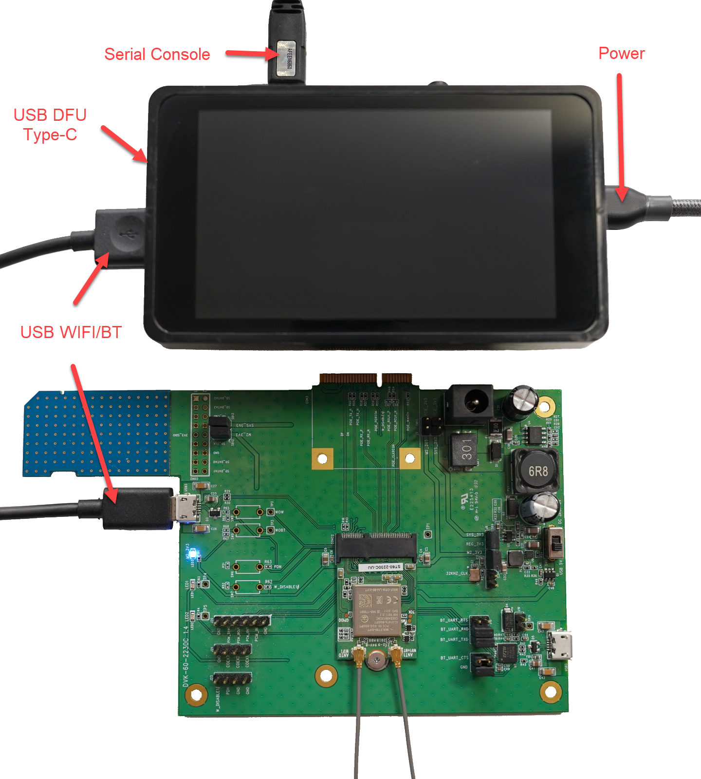
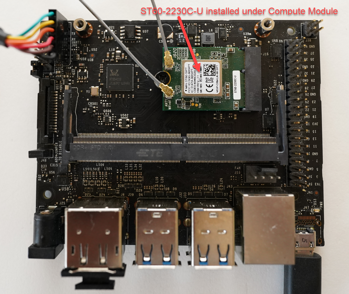
Hardware physical setup
Hardware used is the STM32MP157F-DK2 development kit from ST with the DVK-ST60-2230C with a ST60-2230C-UU variant installed on the DVK. Physical connections include power, serial console, and usb cable between STM32MP157F-DK2 and DVK-ST60-2230C.
Installing OpenSTLinux distribution
These instructions and more are covered here in ST's wiki with the exception of the Wifi driver and firmware integration.
Install OpenSTLinux
cd ~/projects
mkdir openstlinux-5.10-dunfell-mp1-21-11-17
cd openstlinux-5.10-dunfell-mp1-21-11-17

repo init -u https://github.com/STMicroelectronics/oe-manifest.git -b refs/tags/openstlinux-5.10-dunfell-mp1-21-11-17
repo sync
Initialize the Environment
Initialize the environment (in this example, DISTRO openstlinux-weston and MACHINE stm32mp1 are used). Other DISTRO and MACHINE settings can be reviewed on ST Wiki: https://wiki.st.com/stm32mpu/wiki/OpenSTLinux_distribution
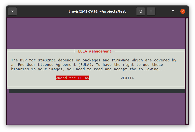
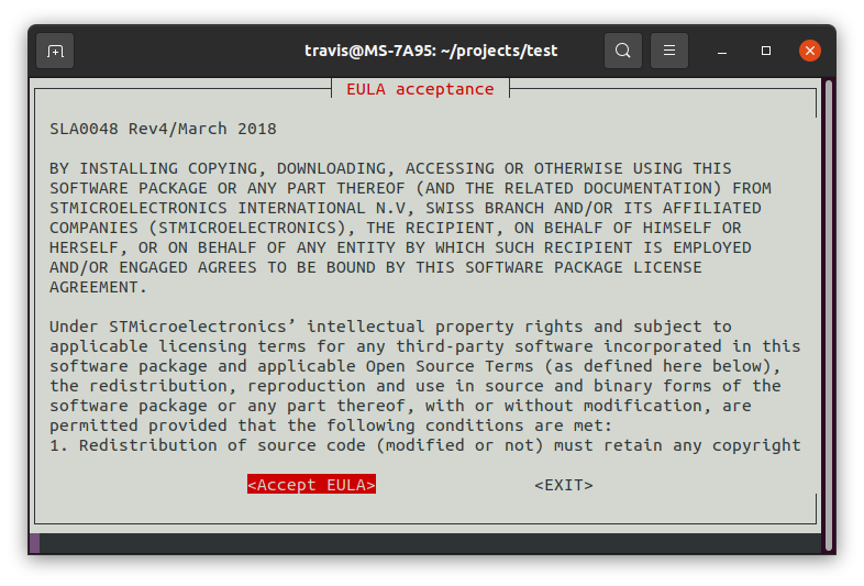
DISTRO=openstlinux-weston MACHINE=stm32mp1 source layers/meta-st/scripts/envsetup.shRead and Accept the EULA.
Integrate meta-layer
Download the meta-layer (meta-laird-cp) release 9.32.0.6
Place the meta-laird-cp layer inside the folder: layers/
cd layers/
git clone https://github.com/Ezurio/meta-summit-radio
Note at the time of this guide release 9.32.0.6 was used. If there are issues integrating the latest driver try switching to this release. Always open a support ticket at https://www.ezurio.com/resources/support (scroll to bottom and hit "Open a Support Ticket") if there are technical questions or issues.
Remove WLAN, bluetooth, and wireless from the kernel
Build the kernel menuconfig and remove WLAN, bluetooth, and wireless from the kernel. The meta-laird-cp will replace these drivers and firmware.
>>cd ~/projects/openstlinux-5.10-dunfell-mp1-21-11-17/build-openstlinuxweston-stm32mp1
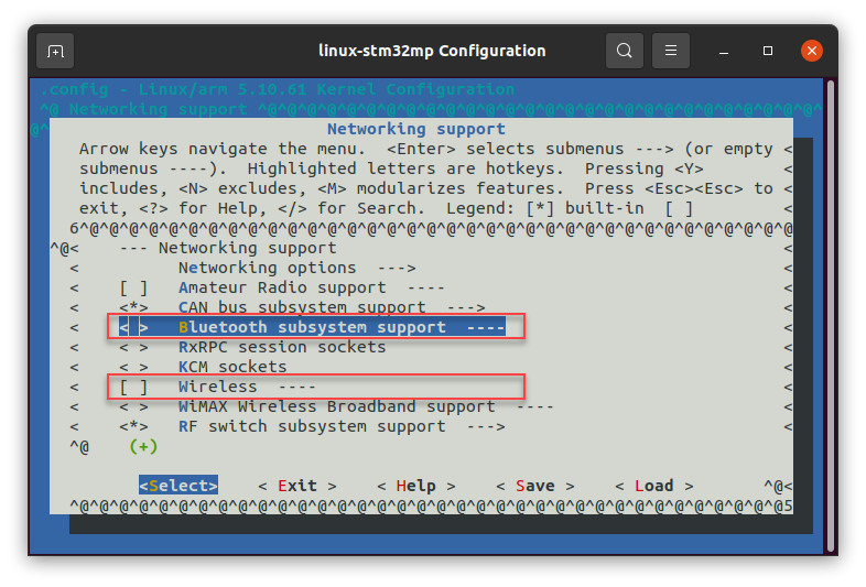
bitbake -c menuconfig virtual/kernel- deselect Device Drivers -> Network device support -> Wireless LAN
- deselect Networking support -> Bluetooth subsystem support
- deselect Networking support -> Wireless
add to conf/bblayers.conf
This adds our meta-laird-cp to the Yocto layers. The path used below will need to be altered depending on the path used on the PC.
>>vi conf/bblayers.conf

BBLAYERS =+ "/home/travis/projects/openstlinux-5.10-dunfell-mp1-21-11-17/layers/meta-laird-cp"
add to conf/local.conf
Set the wpa supplicant provider, BBMASK for openssl, and append to the image packages needed. If using a different hardware interface than USB/USB be sure to change the sterling60-firmware-xxx-xxx to the specific interface to be used.
>>vi conf/local.conf

PREFERRED_PROVIDER_wpa-supplicant = "sterling-supplicant"
PREFERRED_PROVIDER_wpa-supplicant-cli = "sterling-supplicant"
PREFERRED_PROVIDER_wpa-supplicant-passphrase = "sterling-supplicant"

BBMASK += " \
    meta-laird-cp/recipes-packages/openssl \
    meta-laird-cp/recipes-packages/.*/.*openssl10.* \
    "

# For the 60 series radios this needs to point to the specific firmware used, in this case usb/usb
PREFERRED_RPROVIDER_wireless-regdb-static = "sterling60-firmware-usb-usb"

# this must be _append, IMAGE_INSTALL += will cause issues
IMAGE_INSTALL_append += "\
        iproute2 \
        rng-tools \
        ca-certificates \
        tzdata \
        alsa-utils \
        htop \
        ethtool \
        iperf3 \
        tcpdump \
        iw \
        kernel-module-sterling-backports-laird \
        sterling60-firmware-usb-usb \
        sterling-supplicant \
        lrd-networkmanager-sterling \
        lrd-networkmanager-sterling-nmcli \
        "
Sample images are provided in Yocto layer in: meta-laird-cp/recipes-packages/images/. For this guide the IMAGE_INSTALL_append includes everything needed and will be added into st-image-core.
bitbake image
Build the image (in this example st-image-core is used). Other images can be reviewed on ST Wiki: https://wiki.st.com/stm32mpu/wiki/OpenSTLinux_distribution#Images
bitbake st-image-coreflashing image
Flashing the STM32MP157F-DK2 can be done a couple ways.
-
Method 1: Flash over the USB (in DFU mode) using the STM32_Programmer in CLI or GUI. Ensure the mode switches are set to put the device in DFU mode.
-
Method 2: Create a SD card image with the tmp-glibc/deploy/images/stm32mp1/scripts/create_sdcard_from_flashlayout.sh using the How to populate the SD card with dd command instructions.
We're using method 1, flashing over USB in DFU mode. In order to connect in USB DFU mode the mode switches need set accordingly. Set BOOT0 and BOOT2 to OFF to put the device in USB DFU mode and reset the device.
-
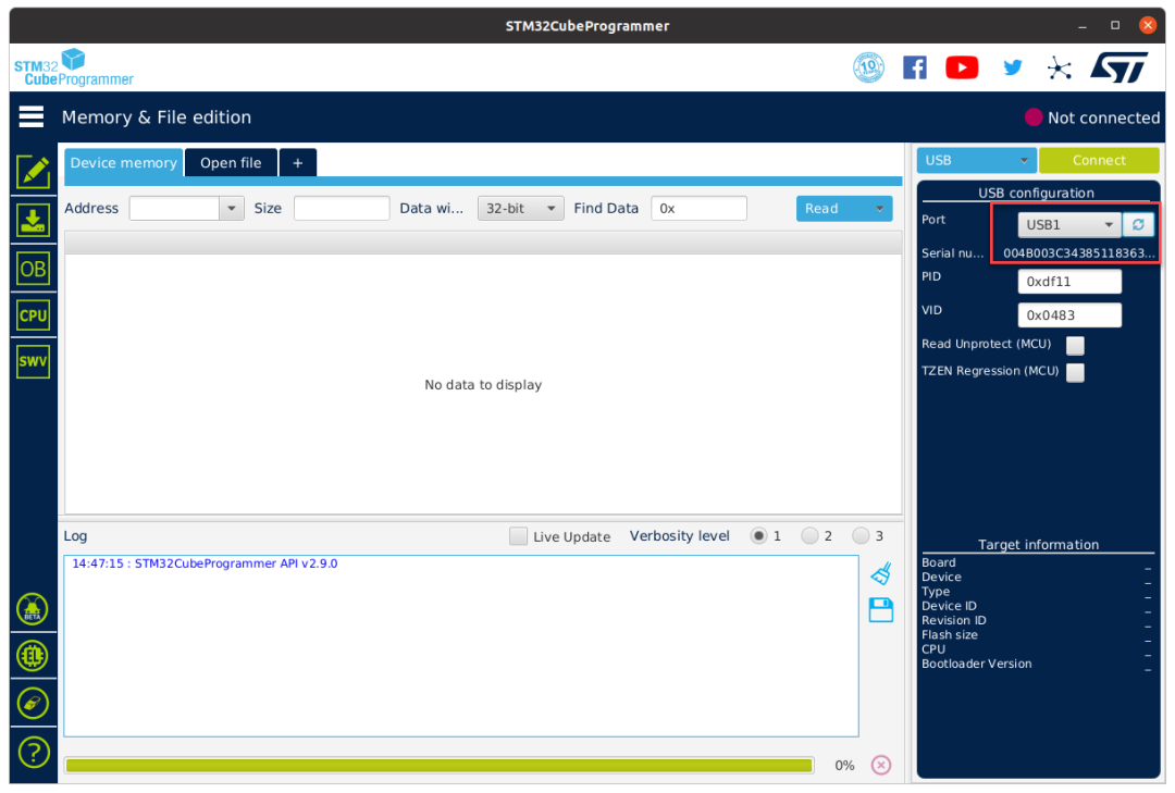
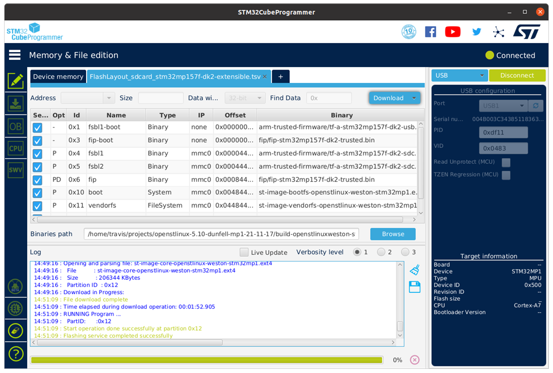
Open up STM32CubeProgrammer:
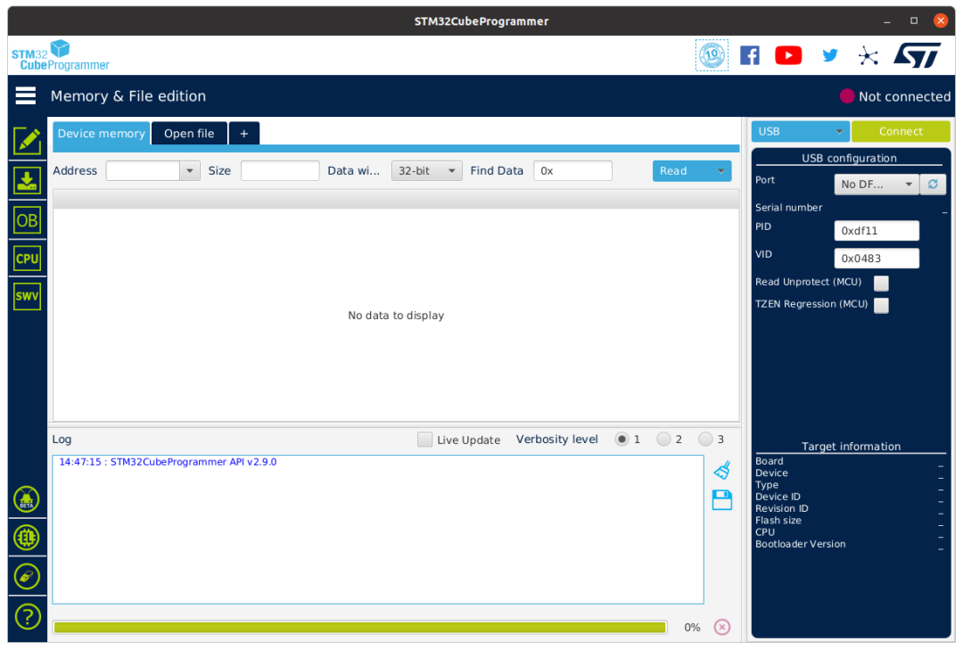
-
Select USB port and select refresh to show STM32MP157F-DK2 is in DFU mode:
-
Select Open File:

-
Select the corresponding tsv file to flash:
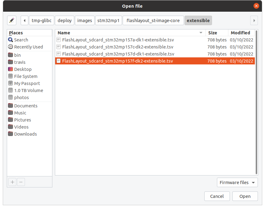
-
Browse to files in: ~/projects/openstlinux-5.10-dunfell-mp1-21-11-17/build-openstlinuxweston-stm32mp1/tmp-glibc/deploy/images/stm32mp1
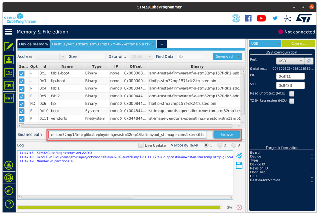
-
Start Download:
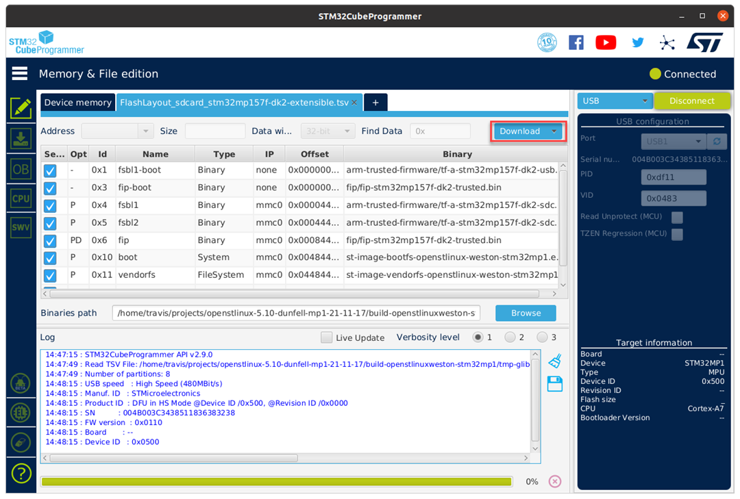
-
Wait for flashing service completed successfully:
-
Flashing Completed:
-
Reset the mode switches back to boot from microSD card (BOOT0 and BOOT2 set to ON) and reset the device.
-
Connect to the serial console to interact with the linux console.
DVK-ST60-2230C checks
Wifi dmesg check
In the dmesg check that backports (driver) is loaded, ieee80211 phy1 comes up and downloads firmware to the Wi-Fi module, and that Bluetooth comes up.
[   14.528114] Loading modules backported from Summit Linux version LRD-REL-9.32.0.6-0-gb207f99f9276
[   14.535616] Backport generated by backports.git v9.32.0.6
[   15.036803] PMU_EN GPIO not configured
[   15.039272] ieee80211 phy0: priv->pcmd_buf = eb1f6934
[   15.065439] ieee80211 phy0: lrdmwl: found firmware image <lrdmwl/88W8997_usb.bin>
[   15.086164] ieee80211 phy0: start to download FW...
[   15.380172] ieee80211 phy0: info: FW download over, size 379228 bytes, ret 0
[   15.385973] ieee80211 phy0: Firmware download complete, port will reset with new interface...
[   15.394611] lrdmwl_usb: probe of 2-1.1:1.0 failed with error -115
[   15.436567] usbcore: registered new interface driver lrdmwl_usb
[   16.535983] stm32-dwmac 5800a000.ethernet eth0: PHY [stmmac-0:00] driver [RTL8211F Gigabit Ethernet] (irq=POLL)
[   16.575961] dwmac4: Master AXI performs any burst length
[   16.579862] stm32-dwmac 5800a000.ethernet eth0: No Safety Features support found
[   16.596237] stm32-dwmac 5800a000.ethernet eth0: IEEE 1588-2008 Advanced Timestamp supported
[   16.616139] stm32-dwmac 5800a000.ethernet eth0: registered PTP clock
[   16.628882] stm32-dwmac 5800a000.ethernet eth0: configuring for phy/rgmii-id link mode
[   16.973181] usb 2-1.1: USB disconnect, device number 3
[   17.285987] usb 2-1.1: new high-speed USB device number 4 using ehci-platform
[   17.460219] PMU_EN GPIO not configured
[   17.462705] ieee80211 phy1: priv->pcmd_buf = 5e3302fe
[   17.463938] ieee80211 phy1: lrdmwl: found firmware image <lrdmwl/88W8997_usb.bin>
[   17.490626] ieee80211 phy1: Skipping FW download, continuing with initialization...
[   17.565267] ieee80211 phy1: OTP data len = 0
[   17.568747] ieee80211 phy1: Adjusting combo 0's number of supported interfaces to 2
[   17.584212] ieee80211 phy1: mwl_reg_notifier set=0 core 00
[   17.598326] ieee80211 phy1: Sending regulatory hint for 00
[   17.598378] ieee80211 phy1: Radio Type ST60 (0x0)
[   17.601646] ieee80211 phy1: Num mac 2 : OTP Version (1)
[   17.615937] ieee80211 phy1: Firmware version: 5.6.43.5
[   17.620767] ieee80211 phy1: Firmware OTP region: ff, country: 00
[   17.632680] ieee80211 phy1: Deep Sleep is disabled
[   17.644073] ieee80211 phy1: 2G enabled, 5G enabled
[   17.647798] ieee80211 phy1: 2 TX antennas, 2 RX antennas. (00000003)/(00000003)
[   17.667494] ieee80211 phy1: mwl_reg_notifier set=1 driver 00
[   17.669028] ieee80211 phy1: Validating lrdmwl/regpwr.db
[   17.669054] ieee80211 phy1: Module signature marker not found 892
[   17.673785] ieee80211 phy1: checking lrdmwl/regpwr.db for region:ff country:00
[   17.673806] ieee80211 phy1: Region ff country 00 not found in lrdmwl/regpwr.db.
[   18.563230] ieee80211 phy1: WMM Turbo=1
[   18.717696] Bluetooth: Core ver 2.22
[   18.737492] NET: Registered protocol family 31
[   18.740562] Bluetooth: HCI device and connection manager initialized
[   18.758081] Bluetooth: HCI socket layer initialized
[   18.768664] Bluetooth: L2CAP socket layer initialized
[   18.781038] Bluetooth: SCO socket layer initialized
[   18.813850] usbcore: registered new interface driver btusb
[   18.829806] Bluetooth: hci0: unexpected event for opcode 0x0000
Wifi interface check
Note: the OUI c0:ee:40 is Ezurio. OUIs can be checked on Wireshark's OUI Lookup Tool.
root@stm32mp1:~# iw dev
phy#1
        Interface wlan0
                ifindex 4
                wdev 0x100000001
                addr c0:ee:40:46:c0:20
                type managed
                txpower 20.00 dBm
root@stm32mp1:~#
Connect to wifi network example
Example of connecting to a network with NetworkManager (nmcli) to SSID "test" and password "password1".
nmcli con add con-name "test" ifname wlan0 type wifi ssid "test" wifi-sec.key-mgmt wpa-psk wifi-sec.psk "password1" Wifi Performance
root@stm32mp1:~# iperf3 -c 10.0.0.3
Connecting to host 10.0.0.3, port 5201
[  5] local 192.168.8.224 port 40996 connected to 10.0.0.3 port 5201
[ ID] Interval           Transfer     Bitrate         Retr  Cwnd
[  5]   0.00-1.00   sec  13.2 MBytes   110 Mbits/sec    0    621 KBytes
[  5]   1.00-2.00   sec  16.6 MBytes   139 Mbits/sec    0   1.21 MBytes
[  5]   2.00-3.00   sec  15.7 MBytes   132 Mbits/sec    0   1.55 MBytes
[  5]   3.00-4.00   sec  19.5 MBytes   163 Mbits/sec    0   1.73 MBytes
[  5]   4.00-5.00   sec  19.2 MBytes   161 Mbits/sec    0   1.91 MBytes
[  5]   5.00-6.00   sec  18.0 MBytes   151 Mbits/sec    1   1.40 MBytes
[  5]   6.00-7.00   sec  15.7 MBytes   132 Mbits/sec    0   1.50 MBytes
[  5]   7.00-8.00   sec  15.3 MBytes   129 Mbits/sec    0   1.50 MBytes
[  5]   8.00-9.00   sec  16.0 MBytes   134 Mbits/sec    0   1.50 MBytes
[  5]   9.00-10.00  sec  18.0 MBytes   151 Mbits/sec    0   1.74 MBytes
- - - - - - - - - - - - - - - - - - - - - - - - -
[ ID] Interval           Transfer     Bitrate         Retr
[  5]   0.00-10.00  sec   167 MBytes   140 Mbits/sec    1             sender
[  5]   0.00-10.03  sec   166 MBytes   139 Mbits/sec                  receiver

iperf Done.
root@stm32mp1:~#

root@stm32mp1:~# iperf3 -c 10.0.0.3 -R
Connecting to host 10.0.0.3, port 5201
Reverse mode, remote host 10.0.0.3 is sending
[  5] local 192.168.8.224 port 40992 connected to 10.0.0.3 port 5201
[ ID] Interval           Transfer     Bitrate
[  5]   0.00-1.00   sec  11.9 MBytes   100 Mbits/sec
[  5]   1.00-2.00   sec  11.0 MBytes  91.9 Mbits/sec
[  5]   2.00-3.00   sec  11.2 MBytes  93.7 Mbits/sec
[  5]   3.00-4.00   sec  12.6 MBytes   105 Mbits/sec
[  5]   4.00-5.00   sec  12.5 MBytes   105 Mbits/sec
[  5]   5.00-6.00   sec  11.7 MBytes  98.4 Mbits/sec
[  5]   6.00-7.00   sec  9.86 MBytes  82.8 Mbits/sec
[  5]   7.00-8.00   sec  8.98 MBytes  75.3 Mbits/sec
[  5]   8.00-9.00   sec  10.8 MBytes  90.9 Mbits/sec
[  5]   9.00-10.00  sec  12.8 MBytes   107 Mbits/sec
- - - - - - - - - - - - - - - - - - - - - - - - -
[ ID] Interval           Transfer     Bitrate         Retr
[  5]   0.00-10.01  sec   116 MBytes  97.0 Mbits/sec   71             sender
[  5]   0.00-10.00  sec   113 MBytes  95.1 Mbits/sec                  receiver

iperf Done.
root@stm32mp1:~#
Bluetooth scan
root@stm32mp1:~# bluetoothctl
Agent registered
[CHG] Controller C0:EE:40:46:C0:23 Pairable: yes
[bluetooth]# power on
Changing power on succeeded
[CHG] Controller C0:EE:40:46:C0:23 Powered: yes
[bluetooth]# scan on
Discovery started
[CHG] Controller C0:EE:40:46:C0:23 Discovering: yes
[NEW] Device 52:71:79:87:90:86 52-71-79-87-90-86
[NEW] Device E7:A3:99:CE:06:A2 BL654 BME280 Sensor
[bluetooth]#
Additional Resources
-
ST
-
Ezurio
Yocto Integration Guide for 60 Series Wi-Fi modules for lrd-11 on iMX8Mplus-LPDDR4 DVK
Introduction
This guide provides "from-scratch" guidelines on how to integrate lrd-11 software releases for our 60-series radios with NXPs Yocto environment.
In this example, we'll integrate the ST60-2230C radio with the NXP iMX8Mplus-LPDDR4 DVK.
Table 1: ST60 variants
| Part Number | Form Factor | WLAN | BT |
|---|---|---|---|
| ST60-2230C | M.2 2230 | SDIO | UART |
| ST60-2230C-SS | M.2 2230 | SDIO | SDIO |
| ST60-2230C-P | M.2 2230 | PCIE | UART |
| ST60-2230C-PU | M.2 2230 | SDIO | USB |
| ST60-2230C-U | M.2 2230 | USB | UART |
| ST60-2230C-UU | M.2 2230 | USB | USB |
| ST60-SIPT | 13 x14mm System in Package | see datasheet for strapping options | see datasheet for strapping options |
Requirements
-
iMX8MP DVK (or other platform with E-key M.2 interface with respective interfaces for WLAN and BT. See Table 1)
-
One of above mentioned ST60 M.2 cards or 60-SIPT DVK.
-
Linux Development PC with Internet access for Yocto build environment.
-
Terminal software for console access to target platform.
Building Initial Linux Image
On your Linux development PC, install the Yocto build environment for your desired target for your desired kernel version.
In this guide, we'll be using:
NXP i.MX Yocto Project User\'s Guide Rev. (IMXLXYOCTOUG) LF6.1.36_2.1.0 --- 29 September 2023
https://www.nxp.com/docs/en/user-guide/IMX_YOCTO_PROJECT_USERS_GUIDE.pdf
Note: On the build PC in this guide Ubuntu 20.04 was used as the Linux distribution.
Build the first image for your target by following the instructions in the in above mentioned user guide.
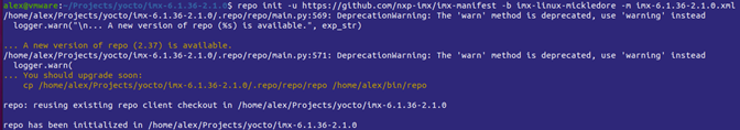
Figure 1: Successful initialization of repo
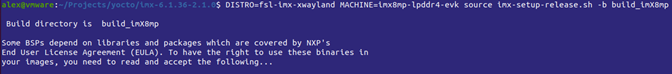
Figure 2: Setup of distribution
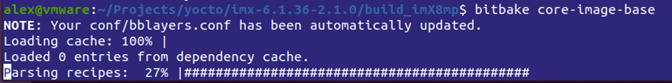
Figure 3: Start building the Linux image
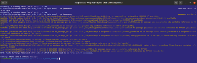
Figure 4: Successful build
Placing Yocto Layer into Build Environment and setting it up
-
The Yocto Layer can be found here:
-
Place the Yocto Layer into the "sources" directory of your Yocto build environment:
alex@vmware:~/Projects/yocto/imx-6.1.36-2.1.0/sources$ git clone https://github.com/Ezurio/meta-summit-radio.git Cloning into 'meta-summit-radio'... remote: Enumerating objects: 1658, done. remote: Counting objects: 100% (123/123), done. remote: Compressing objects: 100% (37/37), done. remote: Total 1658 (delta 90), reused 99 (delta 84), pack-reused 1535 Receiving objects: 100% (1658/1658), 267.85 KiB | 4.62 MiB/s, done. Resolving deltas: 100% (1046/1046), done. alex@vmware:~/Projects/yocto/imx-6.1.36-2.1.0/sources $ ls base meta-browser meta-freescale meta-freescale-distro meta-nxp-demo-experience meta-qt6 meta-summit-radio meta-virtualization meta-arm meta-clang meta-freescale-3rdparty meta-imx meta-openembedded meta-security meta-timesys poky alex@vmware:~/Projects/yocto/imx-6.1.36-2.1.0/sources$ cd meta-summit-radio alex@vmware:~/Projects/yocto/imx-6.1.36-2.1.0/sources/meta-summit-radio$ git checkout lrd-11.39.0.x alex@vmware:~/Projects/yocto/imx-6.1.36-2.1.0/sources/meta-summit-radio$ ls COPYING.MIT meta-summit-radio meta-summit-radio-pre-3.4 radio-stack-4550-hashes.inc radio-stack-60-hashes.inc radio-stack-lwb-hashes.inc README toolsNote: Please consult the README file in the default tree of the meta-summit-radio layer as of which branch to check out as the latest release. In above example "lrd-11.39.0.x" was used.
-
Adapt kernel config
alex@vmware:~/Projects/yocto/imx-6.1.36-2.1.0/build_imX8mp$ bitbake -c menuconfig virtual/kernelNow make the following changes to the default linux-imx kernel config
Note: Follow the path or make use of the / search mechanism in menuconfig to find the respective symbols.
To allow backports to replace the inherent Bluetooth and Wireless (Wifi) drivers:
Networking support --->
< > Bluetooth

Networking support ---> Wireless
<M> cfg80211
Note: \<M> is required due to a change in kernel 5.19. The main kernel config, as of 5.19, now requires that cfg80211 be included so that the networking core layer is able to support an external cfg80211 module.
To add in necessary cryptographic addition:
Cryptographic API ---> CRCs (cyclic redundancy checks) --->
<*> CRC32
Device Driver ---> PCI Support
[*] PCI Express Advanced Error Reporting support
To avoid a long delay at boot time:
Device drivers --> Generic Driver options --> Firmware loader --> [ ] Enable the firmware sysfs fallback mechanism Device Drivers ---> DMA Engine support ---> <M> i.MX **S**DMA support -
Include the Laird meta-summit-radio layer in your bblayers.conf file in the "conf" directory of your Yocto build environment:
BBLAYERS = " \ ${BSPDIR}/sources/poky/meta \ ${BSPDIR}/sources/poky/meta-poky \ \ ${BSPDIR}/sources/meta-openembedded/meta-oe \ ${BSPDIR}/sources/meta-openembedded/meta-multimedia \ ${BSPDIR}/sources/meta-openembedded/meta-python \ \ ${BSPDIR}/sources/meta-freescale \ ${BSPDIR}/sources/meta-freescale-3rdparty \ ${BSPDIR}/sources/meta-freescale-distro \ ${BSPDIR}/sources/meta-summit-radio/meta-summit-radio \ " -
Modify the local.conf file in the "conf" directory of your Yocto build environment to include the required packages. At the end of the file add:
CORE_IMAGE_EXTRA_INSTALL += "\ packagegroup-tools-bluetooth \ packagegroup-fsl-tools-audio \ pulseaudio \ firmware-imx-sdma-imx7d \ kernel-module-imx-sdma \ hostapd \ ethtool \ iperf3 \ tcpdump \ iw \ kernel-module-60-backports-summit \ 60-radio-firmware-sdio-uart \ bt-uart-scripts \ summit-supplicant-60 \ summit-supplicant-libs-60 \ adaptive-ww \ summit-networkmanager-60 \ summit-networkmanager-60-nmcli \ " PREFERRED_RPROVIDER_wpa-supplicant = "summit-supplicant-60" PREFERRED_RPROVIDER_wpa-supplicant-cli = "summit-supplicant-60" PREFERRED_RPROVIDER_wpa-supplicant-passphrase = "summit-supplicant-60" PREFERRED_RPROVIDER_wireless-regdb-static = "60-radio-firmware-sdio-uart" BT_SERIAL_PORT="/dev/ttymxc0"Note: Entries between
CORE_IMAGE_EXTRA_INSTALL += "\andkernel-module-60-backports-summit \are optional but recommended for a good user experience. -
Make device tree change to remove the serdev setting for UART1 to allow for serial interface "/dev/ttymxc0" to be created and re-compile the kernel
in file
/home/alex/Projects/yocto/6.1.36_2.1.0/build/tmp/work-shared/imx8mp-lpddr4-evk/kernel-source/arch/arm64/boot/dts/freescale/imx8mp-evk.dtsremove the lines in red and the blank line above in the UART1 node in the device tree:
&uart1 { /* BT */
    pinctrl-names = "default";
    pinctrl-0 = <&pinctrl_uart1>;
    assigned-clocks = <&clk IMX8MP_CLK_UART1>;
    assigned-clock-parents = <&clk IMX8MP_SYS_PLL1_80M>;
    fsl,uart-has-rtscts;
    status = "okay";

    bluetooth {
        compatible = "nxp,88w8997-bt";
    };
};
and recompile the kernel
bitbake linux-imx -f -c compileNote: these changes are not permanent and need to be re-done after a clean build.
-
Build core-image-minimal image
bitbake core-image-base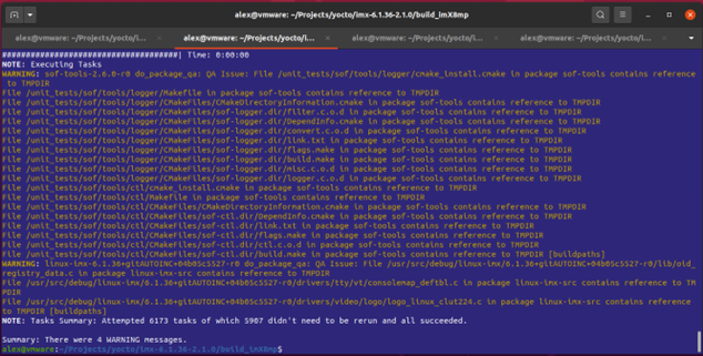
Figure 5: successful build
-
Program a SD card with the newly generated image including kernel and root file system.
alex@vmware:~/Projects/yocto/imx-6.1.36-2.1.0/build_imX8mp/tmp/deploy/images/imx8mp-lpddr4-evk\$ zstd -d core-image-base-imx8mp-lpddr4-evk-20231102140058.rootfs.wic.zst core-image-base-imx8mp-lpddr4-evk-20231102140058.rootfs.wic.zst: 939092992 bytes alex@vmware:~/Projects/yocto/imx-6.1.36-2.1.0/build_imX8mp/tmp/deploy/images/imx8mp-lpddr4-evk\$ ls \*.wic core-image-base-imx8mp-lpddr4-evk-20231102140058.rootfs.wic sudo dd if= core-image-base-imx8mp-lpddr4-evk-20231102140058.rootfs.wic of=/dev/mmcblk0 bs=1M -
Change Device Tree blob in U-Boot to enable SDIO.
When booting for the first time wait for the
Hit any key to stop autoboot: 3message in the console window and hit a key. Then at the u-boot prompt:
u-boot=> pri fdtfile <enter> fdtfile=imx8mp-evk-revb4.dtb u-boot=> setenv fdtfile imx8mp-evk-usdhc1-m2.dtb <enter> u-boot=> saveenv <enter> Saving Environment to MMC... Writing to MMC(1)... OK u-boot=> pri fdtfile <enter> fdtfile=imx8mp-evk-usdhc1-m2.dtb u-boot=> boot <enter>
Verifying functionality
After boot-up enter user name "root" and issue below commands to observe the presence of the Wifi and the Bluetooth interface.
imx8mp-lpddr4-evk login: root root@imx8mp-lpddr4-evk:~# iw dev phy#0 Interface wlan0 ifindex 5 wdev 0x1 addr c0:ee:40:62:30:ec type managed txpower 20.00 dBm root@imx8mp-lpddr4-evk:~# bluetoothctl power on [CHG] Controller C0:EE:40:62:30:EF Class: 0x00200000 Changing power on succeededNow, available board tools can be used to operate Wifi and Bluetooth.
Nvidia Jetson Nano ST60-2230C-U
This tutorial covers the integration of Ezurio's ST60-2230C-U with Wifi interface using USB and Bluetooth interface using UART on a Jetson Nano Developer Kit.
Requirements
Hardware
- A Linux PC (non-VM) with Ubuntu 18 installed
- Jetson Nano (with power supply 5V/4A)
- TTL-RS232-3v3 cable
- USB micro b cable
Hardware Setup
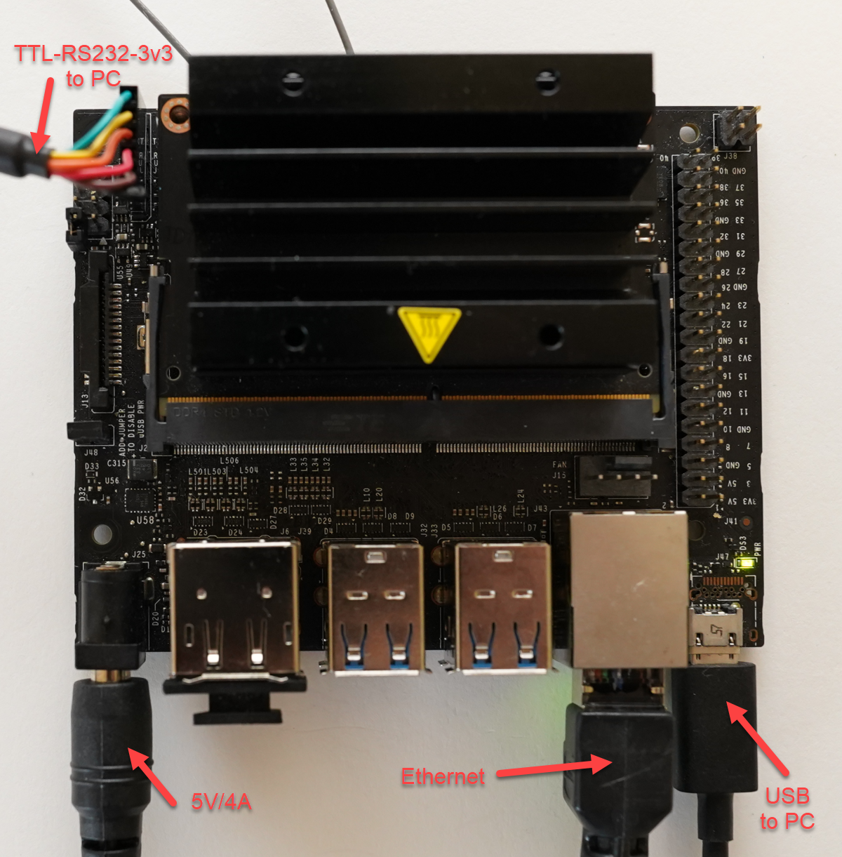
ST60-2230C-U installed
Software
This tutorial uses the Nvidia SDK Manager and assumes the user has experience using this tool.
The SDK Manager Guide can be viewed here: NVIDIA SDK Manager Guide
Download and install Nvidia SDK Manager
https://developer.nvidia.com/nvidia-sdk-manager
sdkmanager_1.8.0-10363_amd64.deb is used in this tutorial.
Known good point
Flash the Jetson Nano to bring to a known good point and allow for sdk to be download on Linux PC.
JetPack 4.6.2 is used in this tutorial.
Build
Get gcc toolchain
Get the Nvidia recommended toolchain Linaro 7.3.1 and install.
cd /opt
sudo wget http://releases.linaro.org/components/toolchain/binaries/7.3-2018.05/aarch64-linux-gnu/gcc-linaro-7.3.1-2018.05-x86_64_aarch64-linux-gnu.tar.xz
sudo tar xvf gcc-linaro-7.3.1-2018.05-x86_64_aarch64-linux-gnu.tar.xz
Get sources using source_sync.sh
cd ~/nvidia/nvidia_sdk/JetPack_4.6.2_Linux_JETSON_NANO_TARGETS/Linux_for_Tegra
./source_sync.sh -t  tegra-l4t-r32.7.1
Note source can alternatively be downloaded from the Jetson Linux R32.7.1 Release Page: https://developer.nvidia.com/embedded/linux-tegra-r3271
Using source from the release page will change the directory structure used in the rest of the tutorial.
Compile kernel
cd ~/nvidia/nvidia_sdk/JetPack_4.6.2_Linux_JETSON_NANO_TARGETS/Linux_for_Tegra/sources/kernel
export JETSON_NANO_KERNEL_SOURCE=$(pwd)
cd $JETSON_NANO_KERNEL_SOURCE

export TOOLCHAIN_PREFIX=/opt/gcc-linaro-7.3.1-2018.05-x86_64_aarch64-linux-gnu/bin/aarch64-linux-gnu-
export TEGRA_KERNEL_OUT=$JETSON_NANO_KERNEL_SOURCE/build
export KERNEL_MODULES_OUT=$JETSON_NANO_KERNEL_SOURCE/modules
make -C kernel-4.9/ ARCH=arm64 O=$TEGRA_KERNEL_OUT LOCALVERSION=-tegra CROSS_COMPILE=${TOOLCHAIN_PREFIX} tegra_defconfig
make -C kernel-4.9/ ARCH=arm64 O=$TEGRA_KERNEL_OUT LOCALVERSION=-tegra CROSS_COMPILE=${TOOLCHAIN_PREFIX} menuconfig
make -C kernel-4.9/ ARCH=arm64 O=$TEGRA_KERNEL_OUT LOCALVERSION=-tegra CROSS_COMPILE=${TOOLCHAIN_PREFIX} -j8
make -C kernel-4.9/ ARCH=arm64 O=$TEGRA_KERNEL_OUT LOCALVERSION=-tegra INSTALL_MOD_PATH=$KERNEL_MODULES_OUT modules_install
During the menuconfig the following items need removed:
- deselect Device Drivers -> Network device support -> Wireless LAN
- deselect Networking support -> Bluetooth subsystem support
- deselect Networking support -> Wireless
- deselect Device Drivers -> Misc drivers -> Bluedroid_pm driver support
Copy kernel over to Nvidia SDK Manager directory (kernel)
cd ~/nvidia/nvidia_sdk/JetPack_4.6.2_Linux_JETSON_NANO_TARGETS/Linux_for_Tegra/sources/kernel/build/arch/arm64/boot
cp -r * ~/nvidia/nvidia_sdk/JetPack_4.6.2_Linux_JETSON_NANO_TARGETS/Linux_for_Tegra/kernel/
Delete old kernel modules in Nvidia SDK Manager directory (kernel)
cd ~/nvidia/nvidia_sdk/JetPack_4.6.2_Linux_JETSON_NANO_TARGETS/Linux_for_Tegra/rootfs/lib/modules/4.9.253-tegra/kernel
sudo rm -rf *
Copy kernel modules from build over to Nvidia SDK Manager directory (rootfs)
cd ~/nvidia/nvidia_sdk/JetPack_4.6.2_Linux_JETSON_NANO_TARGETS/Linux_for_Tegra/sources/kernel/modules
sudo cp -r * ~/nvidia/nvidia_sdk/JetPack_4.6.2_Linux_JETSON_NANO_TARGETS/Linux_for_Tegra/rootfs
Get Ezurio backports and firmware
The latest backports and firmware can be found on the Ezurio Github site: https://github.com/Ezurio/Sterling-60-Release-Packages/releases
This tutorial will use backports and firmware from the 9.32.0.6 release.
Verify the backport and firmware version supports the kernel version to be used on the Jetson Nano. In this case the Jetson Nano is using a 4.9 kernel and the 9.32.0.6 driver which supports kernel 3.2-5.10.
The firmware usb-uart is used for the module ST60-2230C-U with USB wifi and UART Bluetooth.
cd ~/nvidia/nvidia_sdk/JetPack_4.6.2_Linux_JETSON_NANO_TARGETS/Linux_for_Tegra/sources/kernel
wget https://github.com/Ezurio/Sterling-60-Release-Packages/releases/download/LRD-REL-9.32.0.6/backports-laird-9.32.0.6.tar.bz2
wget https://github.com/Ezurio/Sterling-60-Release-Packages/releases/download/LRD-REL-9.32.0.6/laird-sterling60-firmware-usb-uart-9.32.0.6.tar.bz2
Extract firmware to Nvidia SDK Manager directory (rootfs)
sudo tar xvf laird-sterling60-firmware-usb-uart-9.32.0.6.tar.bz2 -C ~/nvidia/nvidia_sdk/JetPack_4.6.2_Linux_JETSON_NANO_TARGETS/Linux_for_Tegra/rootfs/Extract backports and compile
tar xvf backports-laird-9.32.0.6.tar.bz2
cd laird-backport-9.32.0.6

export KLIB_BUILD="/home/laird/nvidia/nvidia_sdk/JetPack_4.6.2_Linux_JETSON_NANO_TARGETS/Linux_for_Tegra/sources/kernel/build"
export KLIB="/home/laird/nvidia/nvidia_sdk/JetPack_4.6.2_Linux_JETSON_NANO_TARGETS/Linux_for_Tegra/sources/kernel/modules"

make ARCH=arm64 CROSS_COMPILE=/opt/gcc-linaro-7.3.1-2018.05-x86_64_aarch64-linux-gnu/bin/aarch64-linux-gnu- defconfig-sterling60
make ARCH=arm64 CROSS_COMPILE=/opt/gcc-linaro-7.3.1-2018.05-x86_64_aarch64-linux-gnu/bin/aarch64-linux-gnu- -j8
Find backport modules and tar and extract to Nvidia SDK Manager directory (rootfs/lib/modules/4.9.253-tegra/updates)
find . -name *.ko -print0 | tar -cvf laird_modules.tar --null -T -

sudo mkdir /home/laird/nvidia/nvidia_sdk/JetPack_4.6.2_Linux_JETSON_NANO_TARGETS/Linux_for_Tegra/rootfs/lib/modules/4.9.253-tegra/updates
sudo tar xvf laird_modules.tar -C /home/laird/nvidia/nvidia_sdk/JetPack_4.6.2_Linux_JETSON_NANO_TARGETS/Linux_for_Tegra/rootfs/lib/modules/4.9.253-tegra/updates
Flash Jetson Nano
cd ~/nvidia/nvidia_sdk/JetPack_4.6.2_Linux_JETSON_NANO_TARGETS/Linux_for_Tegra
sudo ./flash.sh jetson-nano-qspi-sd mmcblk0p1
Final setup and checks on Jetson Nano
Login to the Jetson Nano
There is a setup after flashing that is required to login, this is done with the graphical interface or via serial port console. This tutorial assumes the user knows this and how to finish setting up the Jetson Nano.
Run depmod
This will probe all the modules on the system and allow the new modules to be seen.
sudo depmod -aDisable nvgetty and nvwifibt
sudo systemctl disable nvgetty
sudo systemctl disable nvwifibt
sudo reboot
Add user to groups for Bluetooth UART access
The default Jetson Nano platform will not attach the bluetooth UART unless the user is either added to bluetooth and dialout groups or the btattach command is ran as root with 'sudo su' not as 'sudo btattach'. Running 'sudo btattach' as a user only works randomly where as ran from a 'sudo su' prompt or adding the user to bluetooth and dialout groups works consistently.
sudo usermod -aG bluetooth,dialout lairdcheck wifi
iw dev


root@ubuntu:/home/laird# iw dev
phy#1
        Interface wlan0
                ifindex 7
                wdev 0x100000001
                addr c0:ee:40:46:c0:20
                type managed
                txpower 20.00 dBm
root@ubuntu:/home/laird#
check bluetooth
BT only wants to attach when ran from root prompt ('sudo su' not 'sudo') or user is added to bluetooth and dialout groups.
sudo su
btattach -B /dev/ttyTHS2 -P h4 -S 3000000 &


laird@ubuntu:~$ sudo su
[sudo] password for laird:
root@ubuntu:/home/laird# btattach -B /dev/ttyTHS2 -P h4 -S 3000000 &
[1] 7179
root@ubuntu:/home/laird# Attaching Primary controller to /dev/ttyTHS2
Switched line discipline from 0 to 15
Device index 0 attached

root@ubuntu:/home/laird# bluetoothctl
[NEW] Controller C0:EE:40:46:C0:23 ubuntu [default]
Agent registered
[bluetooth]# scan on
Discovery started
[CHG] Controller C0:EE:40:46:C0:23 Discovering: yes
[NEW] Device 6F:4C:F4:B5:75:7A 6F-4C-F4-B5-75-7A
[NEW] Device 47:62:C0:FF:CC:62 47-62-C0-FF-CC-62
[NEW] Device E7:A3:99:CE:06:A2 BL654 BME280 Sensor
[NEW] Device 7B:37:F3:84:DA:9F 7B-37-F3-84-DA-9F
[NEW] Device 00:FE:8D:8E:F9:BB 00-FE-8D-8E-F9-BB
[NEW] Device 44:98:3B:F9:5B:0A 44-98-3B-F9-5B-0A
[NEW] Device 51:A4:5D:6F:60:1D 51-A4-5D-6F-60-1D
[CHG] Device D2:31:30:30:4F:3B RSSI: -96
[NEW] Device 7C:2F:E2:85:AB:00 7C-2F-E2-85-AB-00
[bluetooth]# exit
Agent unregistered
[DEL] Controller C0:EE:40:46:C0:23 ubuntu [default]
root@ubuntu:/home/laird#
60 Series Application Notes
Setting up 4addr mode
Overview
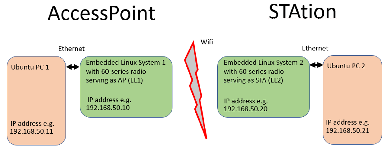
Ezurio's 60 Series radio supports what is known as 4addr mode with our enhanced Summit Wi-Fi stack, allowing for layer-2 bridging between two 60-series radios. This is used, for example, to bridge two wired Ethernet networks. This tutorial describes how to set 4addr mode up and offers sample scripts and sample configuration files for quick results.
For information on how to obtain our SUMMIT Wi-Fi stack, please visit: https://www.ezurio.com/wireless-modules/wifi-modules-bluetooth/summit-software-stack-60-series and contact your local sales representative.
Prerequisites
To set up 4addr mode between two 60 Series radios, you'll need the following:
- 2x embedded linux host systems, each equipped with a 60 Series radio
- Summit Stack running on each 60 Series radio
- "hostapd" and "bridge-utils" packages installed on each system
- Software release 10.4.0.10 or later, available at https://github.com/Ezurio/Sterling-60-Release-Packages/releases
- scripts and configuration files for the 4addr mode configuration, available here
To prove bridging is working as expected, each of the above Linux systems shall be connected to a PC via Ethernet. This tutorial assumes two PCs running a recent Ubuntu version. E.g. LTS version 20.04. or 18.04.
Setup
This diagram show the connection setup this tutorial uses.
Preparation of the Access Point side
Download or create file “4addr_up_AP” and place it in the home directory of the AP board and make it executable with: chmod +x 4addr_up_AP.
ip addr flush dev eth0
sleep 1
ip addr flush dev wlan0
sleep 1
brctl delbr br0
sleep 1
brctl addbr br0
sleep 1
brctl addif br0 eth0
sleep 1
brctl addif br0 wlan0
sleep 1
ip addr add 192.168.50.10/24 dev br0
sleep 1
ip link set br0 up
sleep 1
sdcsupp -iwlan0 -c supp-wds-psk.conf &
Download or create file “supp-wds-psk.conf” and place it in the home directory of the AP board.
network={
    # need ap_config_file with wds entries -- see below
    ap_config_file="/etc/hostapd/hostapd-wds.conf"
    mode=2
    frequency=2437
    ssid="testap"
    scan_ssid=1
    key_mgmt=WPA-PSK
    psk=”1234567890”
    proto=RSN
    pairwise=CCMP
    group=CCMP
}
Download or create file “hostapd-wds.conf” and place it in the directory "/etc/hostapd/” of the AP board.
wds_sta=1
# this needs to match the bridge interface name above
wds_bridge=br0
Connect the AP EL1 board to Ubuntu PC1 and give that PC the IP address 192.168.50.11 in the Ubuntu GUI network settings.
Preparation of the STAtion side
Download or create file “4addr_up_STA” and place it in the home directory of the STA board and make it executable with: chmod +x 4addr_up_STA
ip addr flush dev eth0
sleep 1
ip addr flush dev wlan0
sleep 1
brctl delbr br0
sleep 1
brctl addbr br0
sleep 1
brctl addif br0 eth0
sleep 1
brctl addif br0 wlan0
sleep 1
ip addr add 192.168.50.20/24 dev br0
sleep 1
ip link set br0 up
sleep 1
iw dev wlan0 set 4addr on
sleep 1
sdcsupp -iwlan0 -c supp-sta-psk.conf &
Please note line “iw dev wlan0 set 4addr on” that enable 4addr mode.
Download or create file “supp-sta-psk.conf” and place it in the home directory of the STA board
network={
    ssid="testap"
    scan_ssid=1
    key_mgmt=WPA-PSK
    psk=”1234567890”
    proto=RSN
    pairwise=CCMP
    group=CCMP
}
Connect STAtion EL2 board to Ubuntu PC2 and give that PC the IP address 192.168.50.21 in the Ubuntu GUI network settings.
Note: also make sure that both 60 radios use the same regulatory settings.
Establishing Wifi connection between AP and STA side
On EL1 execute “4addr_up_AP”, wait for it to finish and issue “iw dev”. Observe the AP got created.
root@imx8mp-lpddr4-evk:~# ./4addr_up_AP
bridge br0 doesn't exist; can't delete it
[  111.803027] br0: port 1(eth0) entered blocking state
[  111.808029] br0: port 1(eth0) entered disabled state
[  111.813482] device eth0 entered promiscuous mode
[  111.818189] audit: type=1700 audit(1616581626.196:3): dev=eth0 prom=256 old_prom=0 auid=4294967295 uid=0 gid=0 ses=4294967295
[  112.828648] br0: port 2(wlan0) entered blocking state
[  112.833813] br0: port 2(wlan0) entered disabled state
[  112.839277] device wlan0 entered promiscuous mode
[  112.844108] audit: type=1700 audit(1616581627.220:4): dev=wlan0 prom=256 old_prom=0 auid=4294967295 uid=0 gid=0 ses=4294967295
[  114.859118] br0: port 1(eth0) entered blocking state
[  114.864110] br0: port 1(eth0) entered forwarding state
[  114.869541] IPv6: ADDRCONF(NETDEV_CHANGE): br0: link becomes ready
root@imx8mp-lpddr4-evk:~# [  119.859973] br0: port 2(wlan0) entered disabled state
[  119.868903] ieee80211 phy0: WMM Turbo=1
[  119.927944] IPv6: ADDRCONF(NETDEV_CHANGE): wlan0: link becomes ready
[  119.934567] br0: port 2(wlan0) entered blocking state
[  119.939655] br0: port 2(wlan0) entered forwarding state

root@imx8mp-lpddr4-evk:~#
root@imx8mp-lpddr4-evk:~# iw dev
phy#0
        Interface wlan0
                ifindex 5
                wdev 0x1
                addr c0:ee:40:61:4a:3c
                ssid testap
                type AP
                channel 6 (2437 MHz), width: 20 MHz, center1: 2437 MHz
                txpower 20.00 dBm
root@imx8mp-lpddr4-evk:~#
On EL2 execute “4addr_up_STA” and wait for it to finish and again issue “iw dev” to see the STA is connected to SSID “testap”:
root@imx8mp-lpddr4-evk:~# ./4addr_up_STA
bridge br0 doesn't exist; can't delete it
[ 343.078219] br0: port 1(eth0) entered blocking state
[ 343.083220] br0: port 1(eth0) entered disabled state
[ 343.088468] device eth0 entered promiscuous mode
[ 343.093448] audit: type=1700 audit(1616581856.564:3): dev=eth0 prom=256 old_prom=0 auid=4294967295 uid=0 gid=0 ses=4294967295
[ 344.099714] br0: port 2(wlan0) entered blocking state
[ 344.104802] br0: port 2(wlan0) entered disabled state
[ 344.110438] device wlan0 entered promiscuous mode
[ 344.115533] audit: type=1700 audit(1616581857.588:4): dev=wlan0 prom=256 old_prom=0 auid=4294967295 uid=0 gid=0 ses=4294967295
[ 346.129734] br0: port 1(eth0) entered blocking state
[ 346.134731] br0: port 1(eth0) entered forwarding state
[ 346.140443] IPv6: ADDRCONF(NETDEV_CHANGE): br0: link becomes ready
root@imx8mp-lpddr4-evk:~# [ 351.901072] wlan0: authenticate with c0:ee:40:61:4a:3c
[ 351.916033] wlan0: send auth to c0:ee:40:61:4a:3c (try 1/3)
[ 351.925814] wlan0: authenticated
[ 351.931107] wlan0: associate with c0:ee:40:61:4a:3c (try 1/3)
[ 351.936889] ieee80211 phy0: Setting 20/40 coex cap
[ 351.952667] wlan0: RX AssocResp from c0:ee:40:61:4a:3c (capab=0x411 status=0 aid=1)
[ 351.965552] wlan0: associated
[ 352.077692] IPv6: ADDRCONF(NETDEV_CHANGE): wlan0: link becomes ready
[ 352.084363] br0: port 2(wlan0) entered blocking state
[ 352.089452] br0: port 2(wlan0) entered forwarding state
root@imx8mp-lpddr4-evk:~# iw dev
phy#0
Interface wlan0
ifindex 5
wdev 0x1
addr c0:ee:40:61:48:d4
ssid testap
type managed
channel 6 (2437 MHz), width: 20 MHz, center1: 2437 MHz
txpower 20.00 dBm
4addr: on
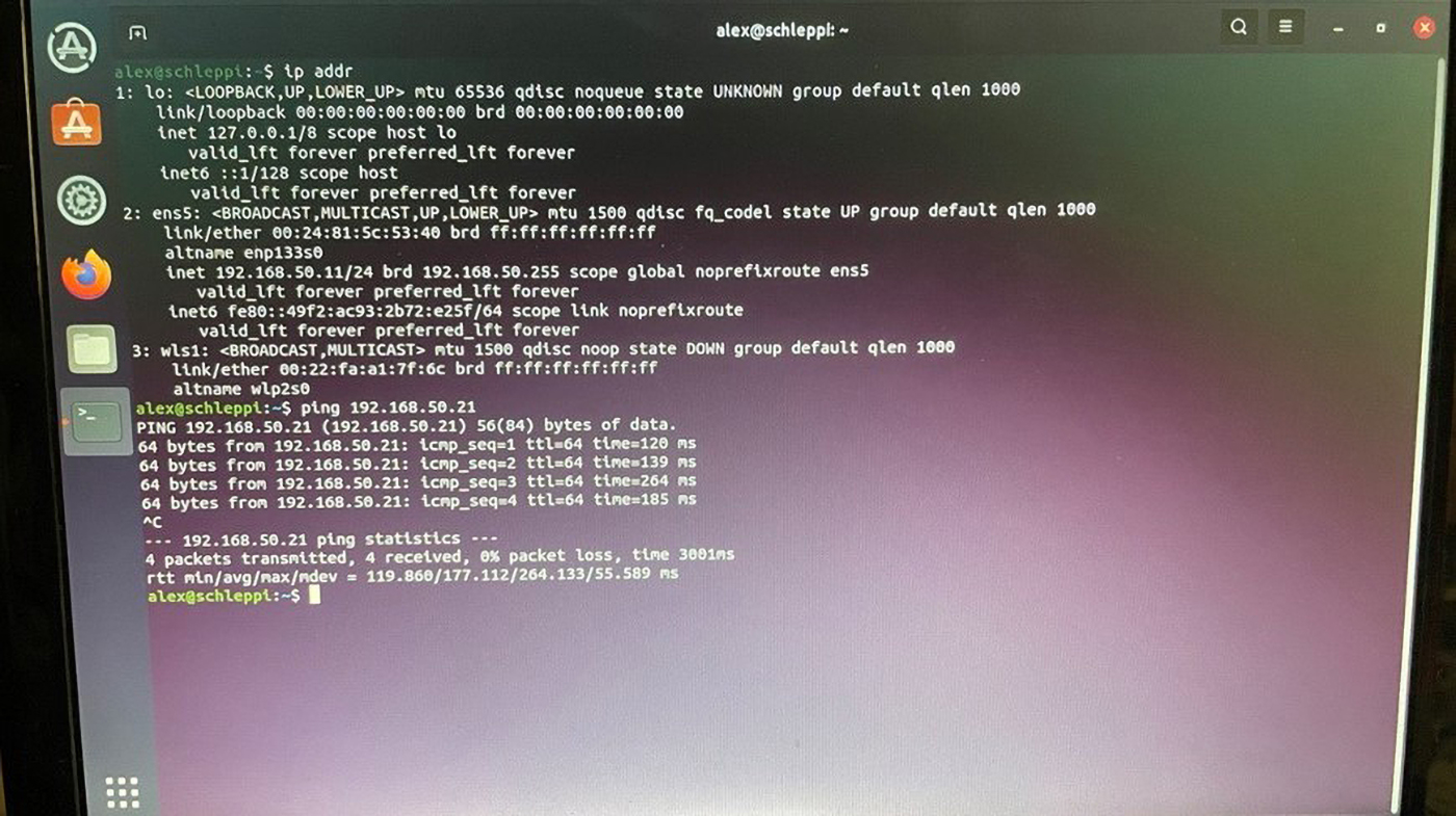
root@imx8mp-lpddr4-evk:~#Now you should be able to ping across from PC1 to PC2 and vice versa.
Ping 192.168.50.21 (PC2) from PC1 (192.168.50.11):
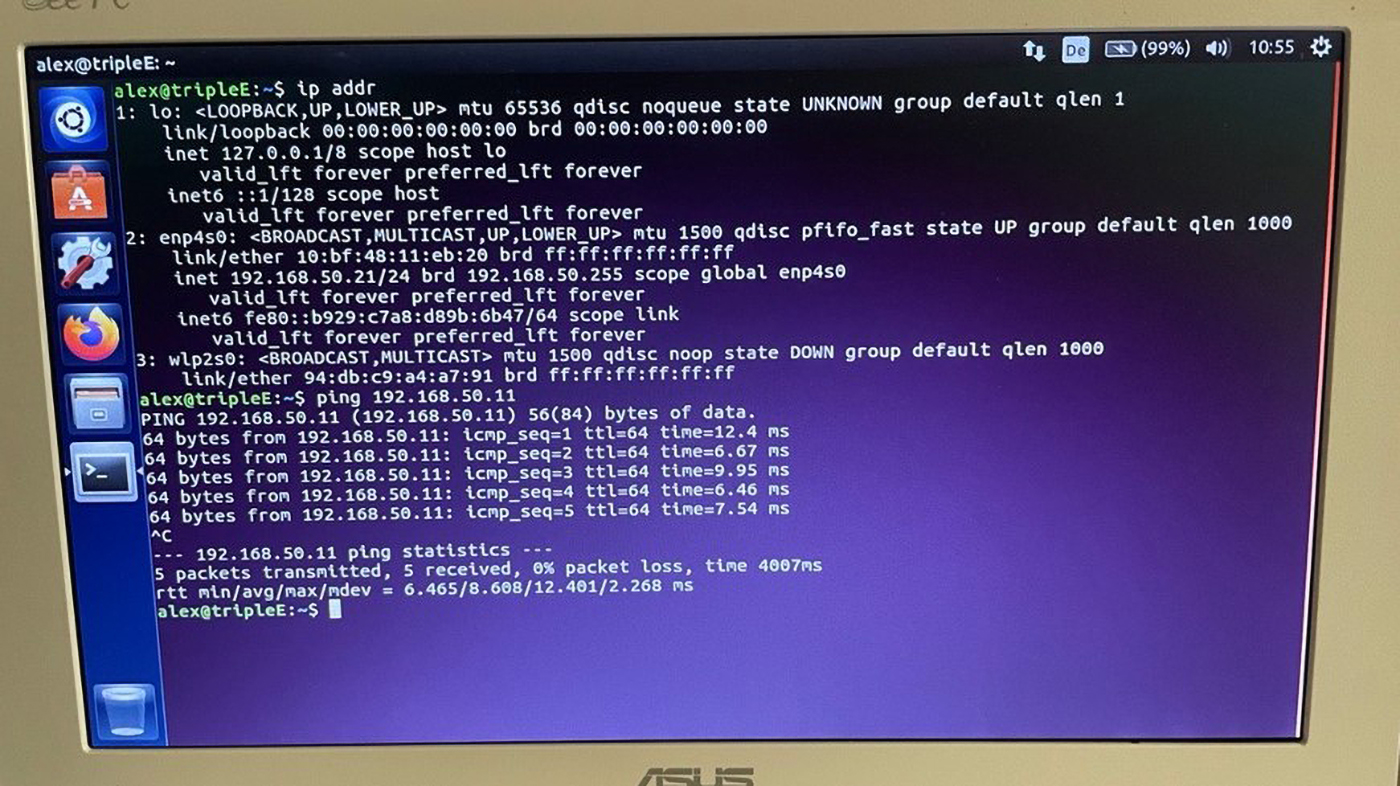
Ping 192.168.50.11 (PC1) from PC2 (192.168.50.21):
Using the 60-radio with Raspberry Pi on the SDIO_UART interface for
Wifi and Bluetooth
Scope
This document demonstrates how to integrate our 60-series Wi-Fi modules with a Raspberry Pi via SDIO interface for Wi-Fi and UART for Bluetooth.
Hardware
For this demonstration, we use the following:
-
Raspberry Pi 4 Model B with a 5V power supply https://www.raspberrypi.com/products/raspberry-pi-4-model-b/
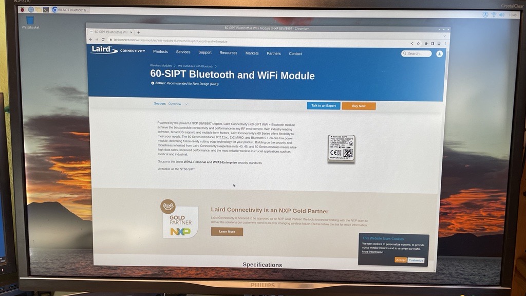
-
DVK-ST60-SIPT DVK with the included 12V power supply: https://www.ezurio.com/wireless-modules/wifi-modules-bluetooth/60-sipt-bluetooth-and-wifi-module/
Hardware setup
This is an example hardware setup. It is wired according to the Raspberry Pi's SDIO overlay, also described below under "Preparation".

pi@RPi4:\~ \$ raspi-gpio get 22-27

GPIO 22: level=0 fsel=7 alt=3 func=SD1_CLK pull=NONE

GPIO 23: level=1 fsel=7 alt=3 func=SD1_CMD pull=UP

GPIO 24: level=1 fsel=7 alt=3 func=SD1_DAT0 pull=UP

GPIO 25: level=1 fsel=7 alt=3 func=SD1_DAT1 pull=UP

GPIO 26: level=1 fsel=7 alt=3 func=SD1_DAT2 pull=UP

GPIO 27: level=1 fsel=7 alt=3 func=SD1_DAT3 pull=UP

Connect 3V3 and GND and GPIO 17 to the center tab of J11 on the ST60 DVK
(PMU_EN) to be able to enable the radio with that GPIO.
Note: This setup is a proof-of-concept, with the SDIO cabling being a functional but non-ideal implementation. This is why the SDIO speed is set only to 2MHz. Please refer to proper SDIO layout for your design.
Preparing SD Card to boot from
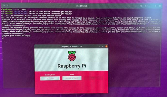
The following demonstrates how to flash a bootable SD card with rpi-imager with SSH enabled on a Ubuntu PC.
-
Start rpi-imager.
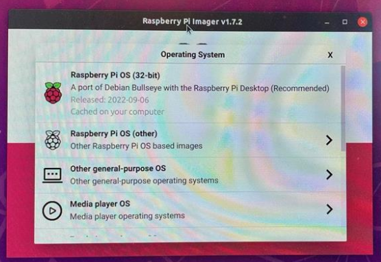
-
Choose OS.
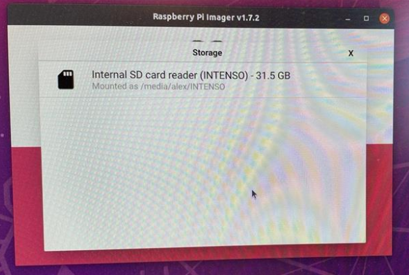
-
Choose SD card (must be inserted in your PC).
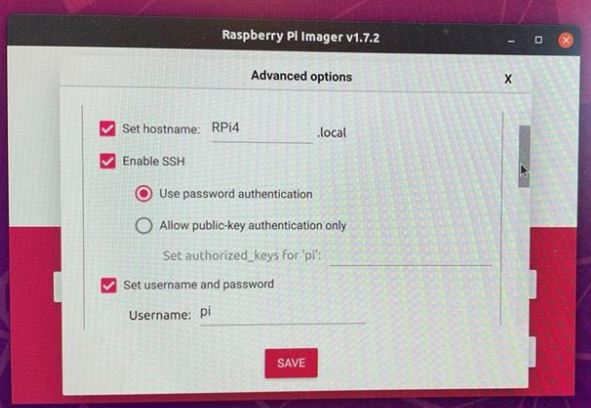
-
Enable SSH to be avaialable after boot.
-
Confirm choice
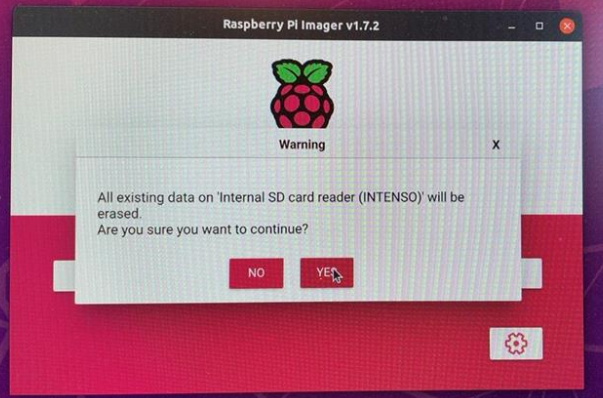
-
Authenticate to access the SD card for writing
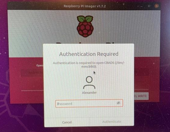
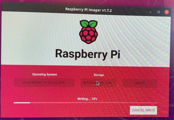
-
Writing to SD card
-
Finished writing
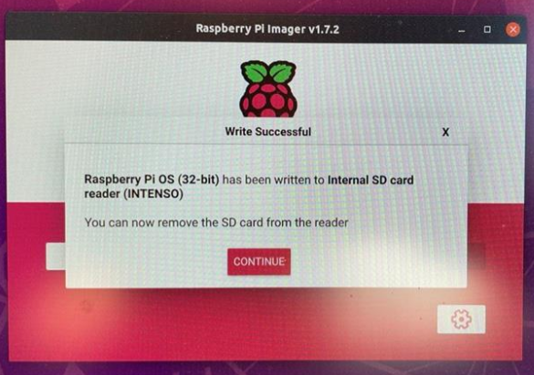
Remove the SD card from the PC and insert it into the Raspberry Pi's SD card slot.
Preparation
The Raspberry Pi offers a neat way to disable and enable on board hardware with overlays.
To do so, edit the file /boot/config.txt on the SD card you just prepared and add this to the end of the file:
#to disable on-board Wifi

dtoverlay=disable-wifi

#to enable SDIO lines for Wifi module on GPIO pins 22-27 (default) at
low speed (2MHz) to accomodate for \"loose\" wiring

dtoverlay=sdio,sdio_overclock=2,poll_once=off
Important: Reboot the device for the changes to take effect.
For reference: https://github.com/raspberrypi/firmware/blob/master/boot/overlays/README
Result after reboot: 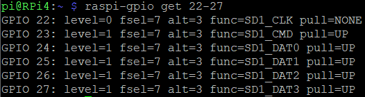
To install required software and download kernel source follow:
https://www.raspberrypi.com/documentation/computers/linux_kernel.html
pi@RPi4:\~/Projects \$ sudo apt install git bc bison flex libssl-dev
make

Reading package lists\... Done

Building dependency tree\... Done

pi@RPi4:\~/Projects \$ git clone \--depth=1
https://github.com/raspberrypi/linux

Cloning into \'linux\'\...

remote: Enumerating objects: 78749, done.

remote: Counting objects: 100% (78749/78749), done.

remote: Compressing objects: 100% (75380/75380), done.

remote: Total 78749 (delta 6494), reused 15987 (delta 2550), pack-reused
0

Receiving objects: 100% (78749/78749), 212.13 MiB \| 5.94 MiB/s, done.

Resolving deltas: 100% (6494/6494), done.

Updating files: 100% (74226/74226), done.

pi@RPi4:\~/Projects \$ ls

linux
Place module firmware in filesystem:
pi@RPi4:\~/Projects \$ sudo wget
<https://github.com/Ezurio/Sterling-60-Release-Packages/releases/download/LRD-REL-10.4.0.10/laird-sterling60-firmware-sdio-uart-10.4.0.10.tar.bz2>

\--2022-09-21 13:49:59\--
https://github.com/Ezurio/Sterling-60-Release-Packages/releases/download/LRD-REL-10.4.0.10/laird-sterling60-firmware-sdio-uart-10.4.0.10.tar.bz2

\... (cut by the author)

Length: 257134 (251K) \[application/octet-stream\]

Saving to: 'laird-sterling60-firmware-sdio-uart-10.4.0.10.tar.bz2'

laird-sterling60-firmware-sdio-uart-10.4.0.1
100%\[===========================================================================================\>\]
251.11K \--.-KB/s in 0.03s

2022-09-21 13:49:59 (7.44 MB/s) -
'laird-sterling60-firmware-sdio-uart-10.4.0.10.tar.bz2' saved
\[257134/257134\]

pi@RPi4:\~/Projects \$ ls

laird-sterling60-firmware-sdio-uart-10.4.0.10.tar linux

pi@RPi4:\~/Projects \$ bunzip2
laird-sterling60-firmware-sdio-uart-10.4.0.10.tar.bz2

pi@RPi4:\~/Projects \$ sudo tar xvf
laird-sterling60-firmware-sdio-uart-10.4.0.10.tar -C /

lib/firmware/lrdmwl/88W8997_sdio.bin

lib/firmware/lrdmwl/88W8997_ST_sdio_uart_v5.5.46.5.bin

lib/firmware/lrdmwl/regpwr.db

lib/firmware/regulatory_sterling60.db

lib/firmware/regulatory.db

pi@RPi4:\~/Projects \$ ls /lib/firmware/lrdmwl/

88W8997_sdio.bin 88W8997_ST_sdio_uart_v5.5.46.5.bin regpwr.db
Download Backports for driver (kernel module) compilation and extract them:
\$ mkdir Projects

pi@RPi4:\~ \$ cd Projects/

pi@RPi4:\~/Projects \$ sudo wget
<https://github.com/Ezurio/Sterling-LWB-and-LWB5-Release-Packages/releases/download/LRD-REL-10.4.0.10/backports-laird-10.4.0.10.tar.bz2>

\--2022-09-21 13:40:15\--
<https://github.com/Ezurio/Sterling-LWB-and-LWB5-Release-Packages/releases/download/LRD-REL-10.4.0.10/backports-laird-10.4.0.10.tar.bz2>

\... (cut by the author)

Length: 9208248 (8.8M) \[application/octet-stream\]

Saving to: 'backports-laird-10.4.0.10.tar.bz2'

backports-laird-10.4.0.10.tar.bz2
100%\[===========================================================================================\>\]
8.78M 7.67MB/s in 1.1s

2022-09-21 13:40:17 (7.67 MB/s) - 'backports-laird-10.4.0.10.tar.bz2'
saved \[9208248/9208248\]

pi@RPi4:\~/Projects \$ bunzip2 backports-laird-10.4.0.10.tar.bz2

pi@RPi4:\~/Projects \$ tar xf backports-laird-10.4.0.10.tar -C .

pi@RPi4:\~/Projects \$ ls

backports-laird-10.4.0.10.tar laird-backport-10.4.0.10
laird-sterling60-firmware-sdio-uart-10.4.0.10.tar linux
Note: this tutorial uses the latest software that was available at the time of its creation. Please adapt the download links to a possibly newer version available at: https://github.com/Ezurio/Sterling-60-Release-Packages/releases
Configuring the kernel
In order for the ST60 module to function correctly, our software package must be used. The ST60 release package is necessary to replace the wireless and the Bluetooth framework that is built in to the Raspberry Pi kernel with our backports and wireless drivers. Additionally, the Raspberry Pi's Bluetooth configuration needs to be taken out of the kernel configuration and the kernel needs to be rebuilt.
As described in the Raspberry Pi documentation linked above, execute the following commands to generate the default .config file.
Note: do not build yet!
cd linux
KERNEL=kernel7l
make bcm2711_defconfig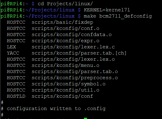
Next, disable Wifi, Bluetooth, RFKILL and Wi-Fi drivers in the kernel, and change the kernel name to distinguish between your build and the default build. Use make menuconfig for that.
Note: libncurses is required by menuconfig. Install that once prior to running make menuconfig.
pi@RPi4:\~/Projects/linux \$ sudo apt-get install libncurses5-dev libncursesw5-dev

\... (cut by the author)

pi@RPi4:\~/Projects/linux \$ make menuconfig
The first page appears as follows:
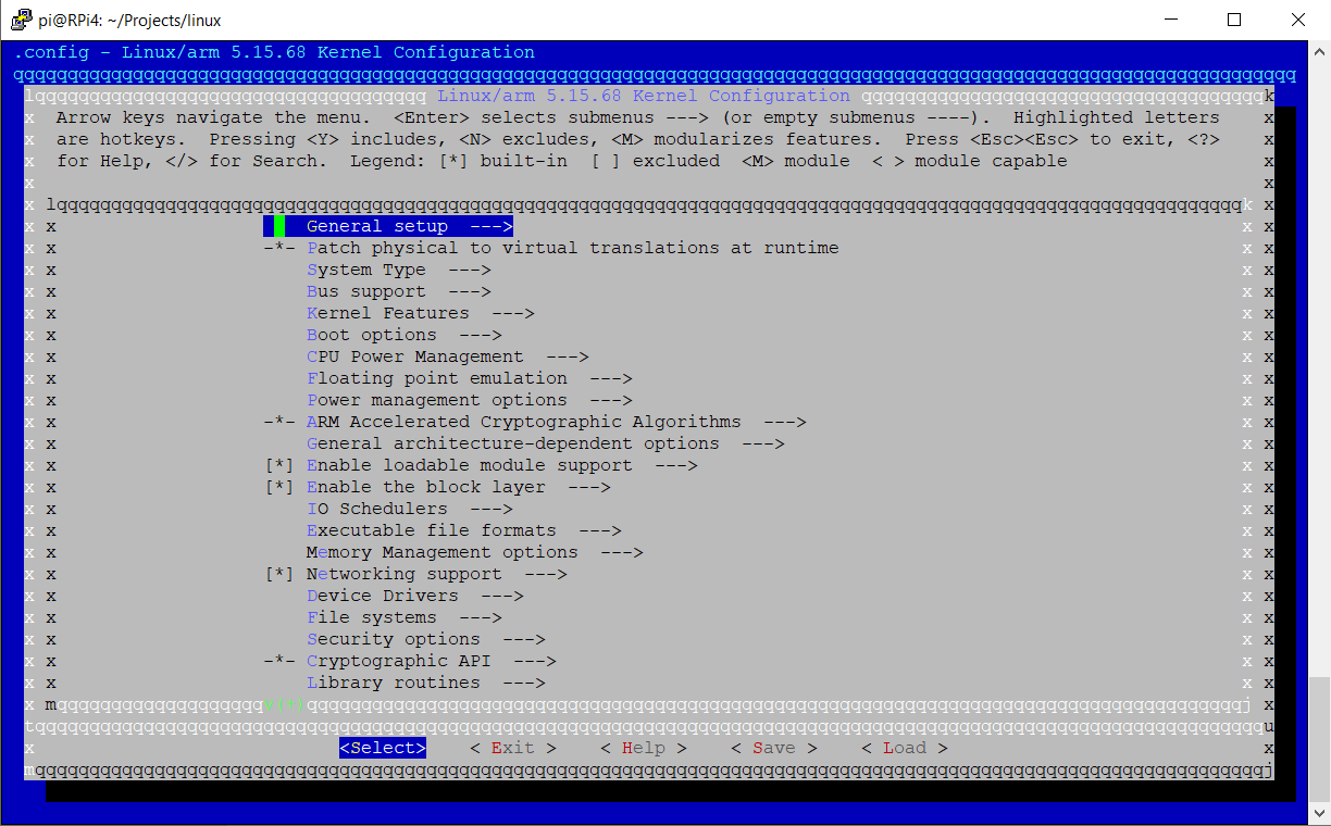
Note: you can hit '/' to activate the search function
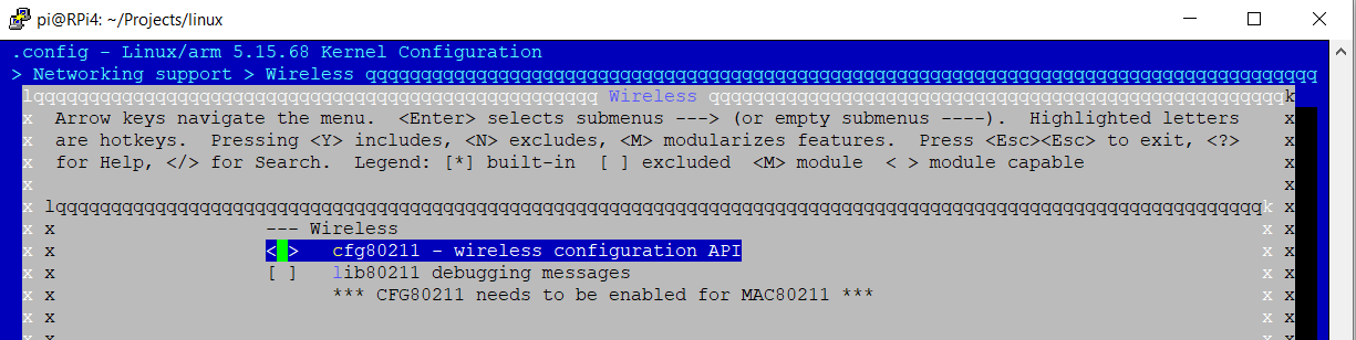
Disable Wireless (cfg80211) as shown:
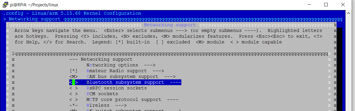
Disable Bluetooth as shown:
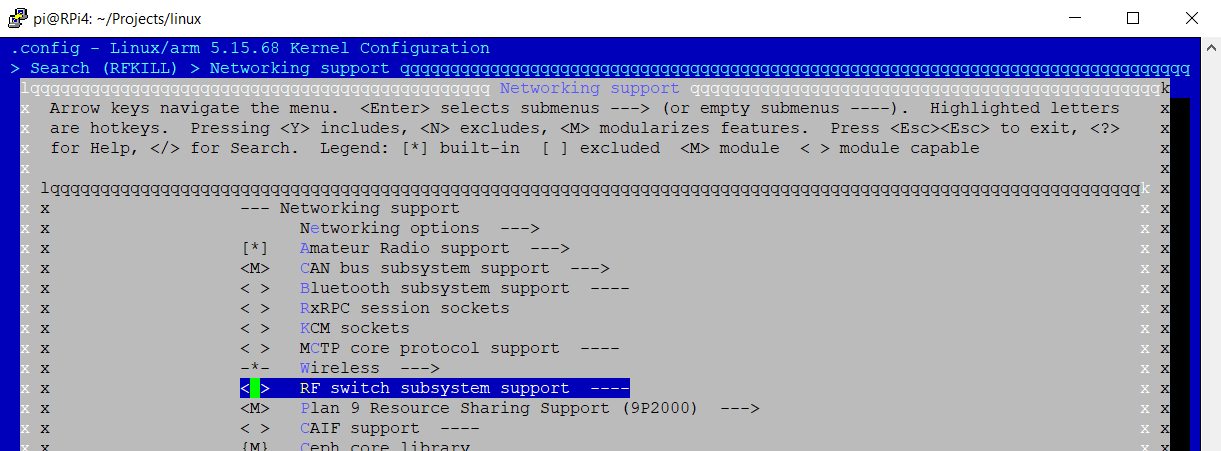
Disable RFKILL as shown:
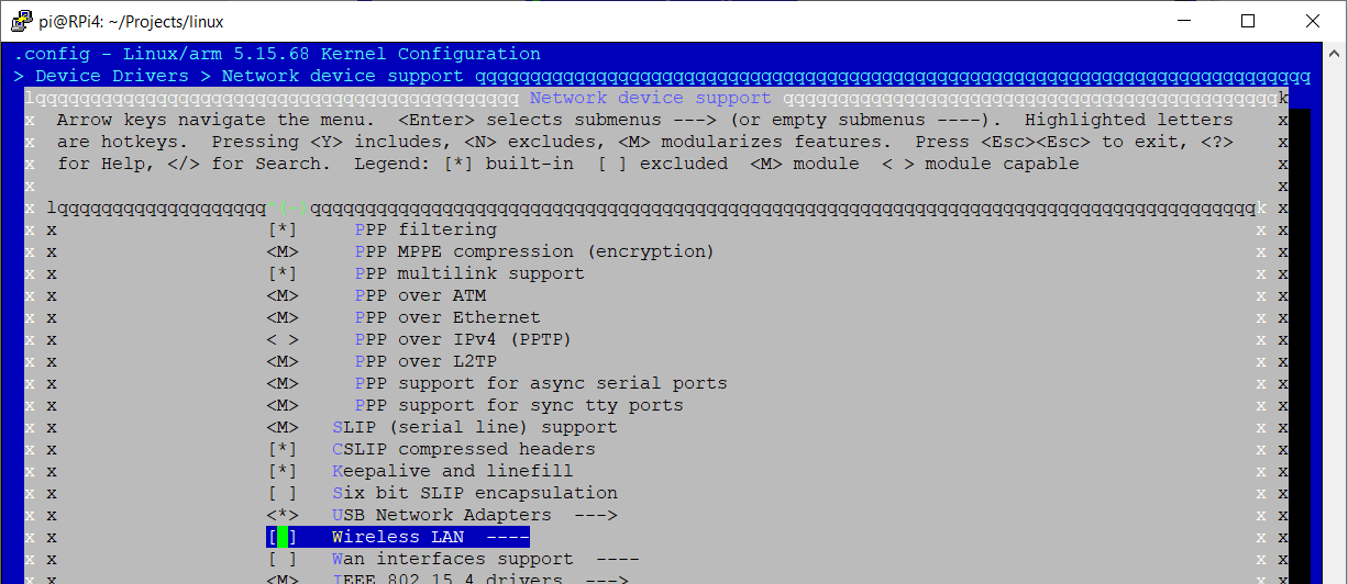
Disable all stock wireless module drivers as shown:
Change LOCALVERSION to reflect the changes made as shown:
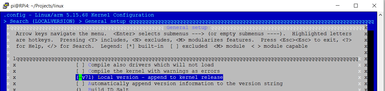
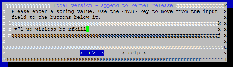
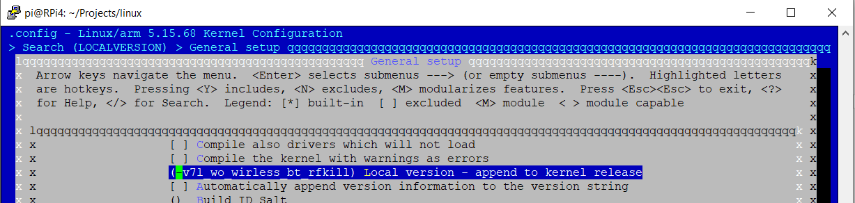
Note: Do not forget to save your changes!
Note: If you run 'make bcm2711_defconfig' again, the above changes will all be reverted.
Now you are ready to build and install the kernel (32-bit).
Building the kernel
Build the kernel and install it using the commands described on this page: https://www.raspberrypi.com/documentation/computers/linux_kernel.html
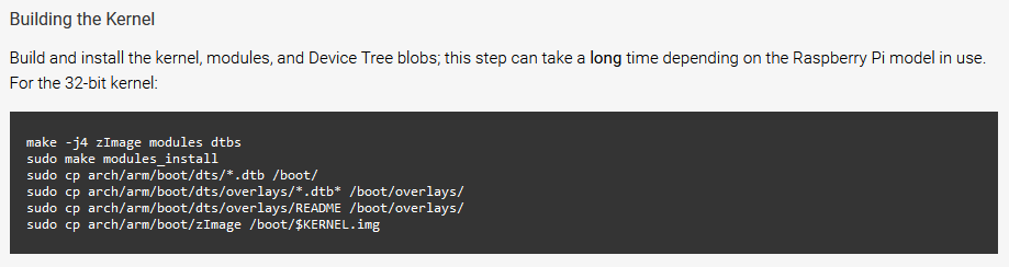
Note: Remember to use the instructions for the 32-bit kernel
make -j4 zImage modules dtbs

sudo make modules_install

sudo cp arch/arm/boot/dts/\*.dtb /boot/

sudo cp arch/arm/boot/dts/overlays/\*.dtb\* /boot/overlays/

sudo cp arch/arm/boot/dts/overlays/README /boot/overlays/

sudo cp arch/arm/boot/zImage /boot/\$KERNEL.img
Note: Remember to REBOOT after copying the kernel image over.
After reboot and issuing "uname -a" you can see the newly generated kernel has been loaded:
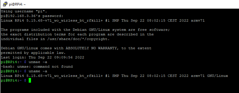
Note: kernel version 5.15.68-v7l_wo_wirless_bt_rfkill
Building and installing Backports
Navigate to the ackport directory and issue the following commands:
make defconfig-sterling60

make -j4

sudo make install

pi@RPi4:\~ \$ make defconfig-sterling60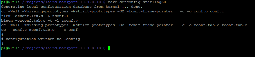
Next, issue the following:
pi@RPi4:\~ \$ make -j4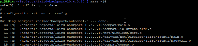
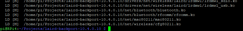
pi@RPi4:\~ \$ sudo make install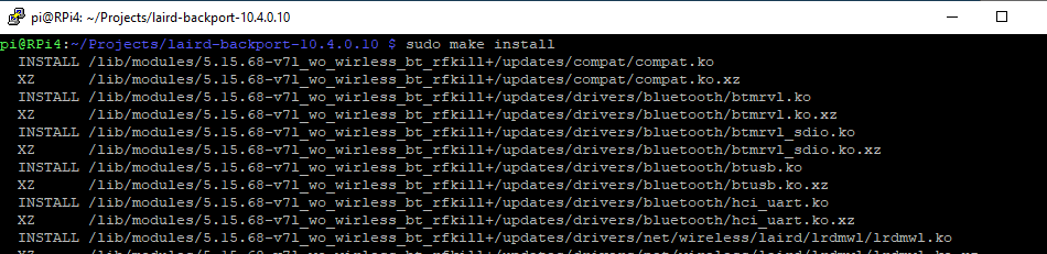
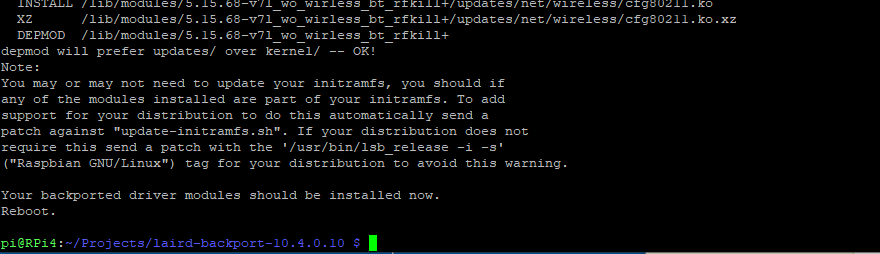
Reboot the Raspberry Pi.
Bringing Up the Wi-Fi Interface
Enable GPIO17 as an output by issuing the following:
pi@RPi4:\~ \$ echo 17 \> /sys/class/gpio/export

pi@RPi4:\~ \$ echo out \> /sys/class/gpio/gpio17/direction
Next, set GPIO high (1) to enable the Wi-Fi module by issuing the following:
pi@RPi4:\~ \$ echo 1 \> /sys/class/gpio/gpio17/value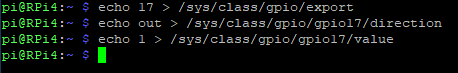
Complete the following to configure and enable the ST60 module:
pi@RPi4:\~ \$ dmesg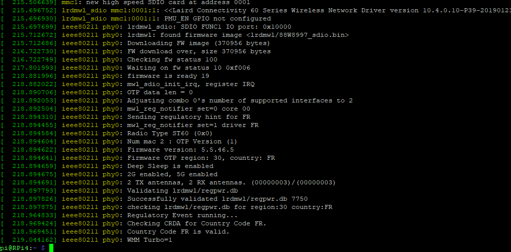
pi@RPi4:\~ \$ iw dev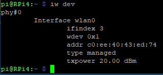
pi@RPi4:\~ \$ ip addr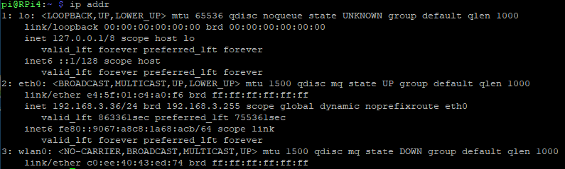
pi@RPi4:\~ \$ sudo iw wlan0 scan \| grep SSID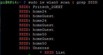
The ST60 module is now running on the Raspberry Pi.
Bringing up Bluetooth
Connect the ST60 DVK to the Raspberry Pi using a micro-USB to USB-A cable:
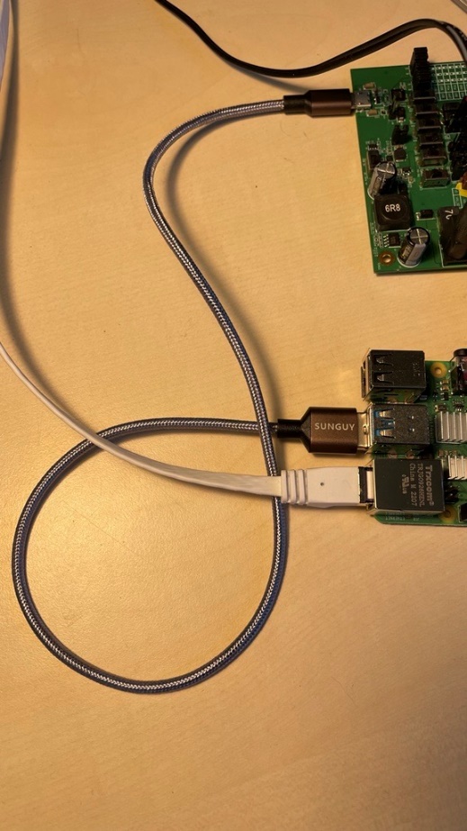
Issue the following commands to bring up Bluetooth on the ST60 within the Raspberry Pi:
pi@RPi4:\~ \$ dmesg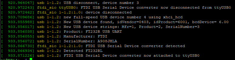
pi@RPi4:\~ \$ sudo btattach -B /dev/ttyUSB0 -P h4 -S3000000 &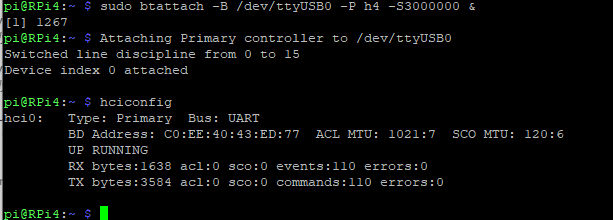
Note: You might have to hit enter for the prompt to re-appear after "hciconfig" finishes.
pi@RPi4:\~ \$ bluetoothctl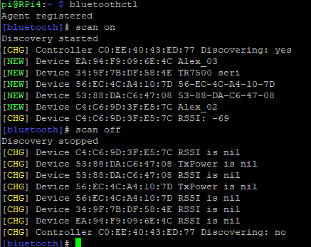
Note: Issue "scan on" and "scan off" inside of Bluetoothctl CLI
In the GUI
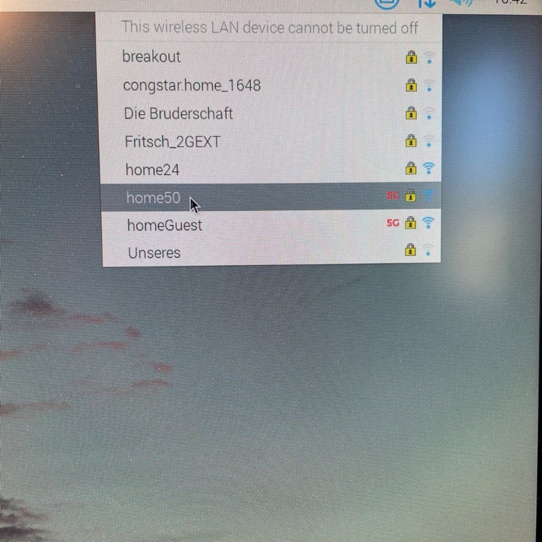
We now disconnect the Ethernet cable from the Raspberry Pi, to ensure we're only communicating over Wi-Fi.
Wireless networks are displayed in the GUI as shown:
Send a test ping as shown:
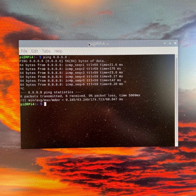
Connected to the internet (ezurio.com):
Antenna Adjust
60-SIPT/60-2230C
Introduction
The 60 Series radio supports a feature called Antenna Adjust that can be used by OEMs to reduce the radio transmit power if needed to meet regulatory requirements.
This feature is intended for scenarios where an OEM uses an antenna with higher gain than the antennas used by Ezurio to obtain modular certifications. This feature can also be used in scenarios where an OEM platform with the 60 Series radio module is failing to meet regulatory requirements due to issues such as a high noise floor or other unrelated spurious emission that causes the device to exceed regulatory limits in some part of the band.
Implementation
The Antenna Adjust feature is implemented as a single 32-bit parameter that is divided into bit fields covering 5 channel groups as follows:
| Bit Field | Channel Group |
|---|---|
| 3:0 | 1-14 (2.4G) |
| 7:4 | 36-48 (UNII-1) |
| 11:8 | 52-64 (UNII-2) |
| 15:12 | 100-144 (UNII-2e) |
| 19:16 | 149-165 (UNII-3) |
| 31:20 | Reserved (must be zero) |
Each bit field specifies the amount of attenuation in dBm that is to be applied when transmitting on any channel in the corresponding channel group. The attenuation is unconditionally applied to all packets transmitted at all rates regardless of regulatory domain. However, the attenuation value has a lower limit which bounds the lowest possible radio power to approximately 1 dBm.
Note: It is not possible to increase the transmit power using this feature.
The Antenna Adjust parameter can be specified either in the device tree (preferred), or as a driver module parameter. Device tree configuration is significantly more resilient against end-user tampering and may be required in order to meet regulatory software security requirements. Module parameter configuration may be easier to use in some test scenarios. If the parameter is specified in both locations, the device tree configuration is used. If the parameter is not specified, then no attenuation is applied.
Note: If the parameter is specified but reserved bits are set, the driver will fail to load.
The dmesg log will contain a string indicating the Antenna Adjust value if it has been configured. This can be used to verify that it has been implemented correctly.
[ 3814.625386] ieee80211 phy0: Antenna gain adjustment in effect: 0x54321Device Tree Configuration
Antenna Adjust is configured in the device tree node for the desired interface using a 32-bit UINT parameter called ant-gain-adjust.
Note: The compatible string must be set correctly as follows for each interface or the device tree node will not be used. In some cases, if an incorrect compatible string is specified, the driver may fail to load.
SDIO Example
&mmc1 { ... slot@0 { reg = <0>; ... wifi: wifi { compatible = "marvell,sd8997"; ... ant-gain-adjust = <0x00054321>; }; }; };PCIE Example
&pcie { ... pcie@0 { reg = <0x0000 0 0 0 0>; #address-cells = <3>; #size-cells = <2>; ... wifi@1 { reg = <0x000000 0 0 0 0>; compatible = "pci1b4b,2b42"; ... ant-gain-adjust = <0x00054321>; }; }; };USB/UART Example
&usb2 { #address-cells = <1>; #size-cells = <0>; ... wifi@2{ compatible = "usb1286,204e"; reg = <2>; ... ant-gain-adjust = <0x00054321>; }; };USB/USB Example
&usb2 { #address-cells = <1>; #size-cells = <0>; ... st60@2{ compatible = "usb1286,204e"; reg = <2>; #address-cells = <2>; #size-cells = <0>; /* Wi-fi functionality is on Configuration 1, Interface 2 */ wifi@2{ compatible = "usbif1286,204e.config1.2"; reg = <2 1>; ... ant-gain-adjust = <0x00054321>; }; }; };Module Parameter Configuration
Antenna Adjust can also be configured with a lrdmwl.ko module parameter. The module parameter is called ant_gain_adjust.
Example:
options lrdmwl ant_gain_adjust=0x00054321Regulatory Testing Issues
The Lightweight Regulatory Utility (LRU) is used in conjunction with special manufacturing firmware to put the radio into various constant transmit modes at full power to verify compliance with regulatory limits. The LRU supports the Antenna Adjust feature using the Antenna Adjust configuration item within the LRU WiFi Configuration Menu.
Note: The manufacturing firmware does not support the Antenna Adjust driver configuration specified in either the device tree or module parameter. Antenna Adjust must be configured in the LRU WiFi Configuration Menu in order for it to be in effect when using the LRU.
There are two typical scenarios where the Antenna Adjust parameter will need to be set when using the LRU. The first is during initial transmit power testing either in development or at a certification laboratory when no Antenna Adjust attenuation limits have yet been determined. If testing shows that regulatory limits are exceeded, the Antenna Adjust configuration option can be set within the LRU WiFi Configuration Menu and the test repeated. Once testing is complete, the Antenna Adjust value that was necessary to pass regulatory testing must be configured in the device tree so it is in effect under normal operating conditions.
The second use case is when testing at a certification lab when there is already an Antenna Adjust value that is known to be required and is already configured in the device tree. That same value must be configured in the LRU WiFi Configuration Menu so it is in effect during testing and matches the attenuation level that will be in effect during normal operation.
Note: If Antenna Adjust is used in the LRU to pass regulatory testing that same value must subsequently be configured in the device tree for use during normal operation. Failure to do so will cause the platform to be in violation of regulatory limits.
See the Vendor Tools app note for details on tool usage.
External Reset
60-SIPT/60-2230C
Introduction
The 60 Series WiFi radio driver supports a mechanism to initiate a reset of the radio module. Reset is sometimes necessary at driver initialization in cases where the driver has been reloaded or after a warm reset (restart) of the host platform if the radio module had not also undergone a hardware reset. The driver will also initiate a reset if the radio module unexpectedly stops responding. The reset functionality can also be used to achieve maximum power savings in some cases. This document details the hardware and software configuration required on the host platform to implement the reset functionality.
Note: The reset implementation is dependent on host platform hardware design for all WiFi interfaces except PCIe. The hardware design must allow the radio module to be reset via GPIO pin under software control for SDIO and USB interfaces. This could either be implemented with GPIO control of a dedicated power rail to the radio module, or by following the datasheet recommendation to control the PMU_EN/WDISABLE_1# signal on the module.
Note: The decision to trigger a reset is based on WiFi requirements only. However, Bluetooth operation is sometimes affected when reset occurs.
Implementation
The hardware and software requirements to implement reset differ based on whether the SDIO, USB or PCIe WiFi interface is used. The Bluetooth impact also varies based on which WiFi interface is used.
PCIe
This section is relevant to all radio modules that use PCIe for the WiFi interface.
The PCIe reset implementation uses the Function Level Reset defined in the PCI specification. This requires no reset specific hardware or software support on the host platform. The reset is limited to WiFi interface only; Bluetooth is not affected.
SDIO and USB
This section is relevant to all radio modules that use either SDIO or USB for the WiFi interface.
The SDIO and USB reset mechanism relies on a host platform provided GPIO to control the power management IC on the radio module. Platforms that use the SIPT module need to control the PMU_EN signal. Platforms that use an M.2 module with an SDIO or USB WiFi interface (2230C, 2230C-SS, 2230C-U, 2230C-UU) need to control the W_DISABLE1# signal, which is directly connected to PMU_EN on the M.2 card. In both cases, a high signal will enable the radio circuitry and a low signal will disable the radio circuitry.
Note: The PMU_EN signal controls a PMIC that provides power to both WiFi and Bluetooth portions of the module. The Bluetooth radio will also be reset if the WiFi driver initiates a reset for any reason.
Note: The 88W8997 datasheet requires that the PMU_EN signal be de-asserted for a minimum of 100ms to guarantee a complete reset.
MMC pwrseq Implementation
The GPIO used for reset is configured in the device tree. There are two ways to configure the reset GPIO depending on whether an SDIO or USB based WiFi radio is used. The MMC bus driver that hosts the lrdmwl SDIO WiFi client driver natively supports a reset power sequencing mechanism called mmc pwrseq. This is a good option to use with SDIO based radios. In this model the reset is entirely managed by the MMC bus driver, and the bus driver is fully aware of the WiFi radio state.
The following sample device tree snippet demonstrates the MMC pwrseq configuration that can be used with SDIO based radios. The reset GPIO is specified via the property reset-gpios following standard gpio binding. The MMC pwrseq feature is designed to control a "reset" signal, not a power enable signal. MMC pwrseq asserts the configured reset signal prior to enabling bus power, and deasserts the signal after power up is complete. Since the reset GPIO is actually connected to the PMU_EN signal, the reset signal must be configured as an active low signal. This will cause the PMU_EN signal to be deasserted during the period the MMC bus driver intends to hold the radio in reset, and asserted (enabling power) otherwise. See the MMC pwrseq devicetree binding documentation in the kernel for more details on MMC pwrseq.
&pinctrl { board { pinctrl_wifi_pmu_en: wifi_pmu_en { atmel,pins = <AT91_PIOE 5 AT91_PERIPH_GPIO AT91_PINCTRL_PULL_UP>; }; ... } } wifi_pwrseq: wifi_pwrseq { pinctrl-names = "default"; pinctrl-0 = <&pinctrl_wifi_pmu_en>; compatible = "mmc-pwrseq-simple"; reset-gpios = <&pioE 5 GPIO_ACTIVE_LOW>; post-power-on-delay-ms = <10>; power-off-delay-us = <100000>; }; &mmc1 { pinctrl-0 = <&pinctrl_mmc1_clk_cmd_dat0 &pinctrl_mmc1_dat1_3 &pinctrl_wifi_wake>; mmc-pwrseq = <&wifi_pwrseq>; ... };lrdmwl Implementation
The lrdmwl WiFi driver itself supports a custom reset mechanism that is also configured in the device tree. This option must be used with USB based radios since the USB bus driver doesn't have native power reset sequencing support like MMC. This option can also be used with SDIO based radios.
See the following sample device tree snippets for SDIO and USB interfaces using the custom lrdmwl reset implementation. The GPIO is specified via the property pmu-en-gpios following standard gpio binding. This pin should default to a logical high so that the radio is initially powered up and able to be enumerated on the bus. Note that the compatible property must also be present in the wifi node.
&pinctrl { board { pinctrl_wifi_pmu_en: wifi_pmu_en { atmel,pins = <AT91_PIOE 5 AT91_PERIPH_GPIO AT91_PINCTRL_PULL_UP>; }; ... } } &mmc1 { ... /* keep-power-in-suspend; */ slot@0 { ... non-removable; wifi: wifi { compatible = "marvell,sd8997"; ... pmu-en-gpios = <&pioE 5 GPIO_ACTIVE_HIGH>; /* remove-power-on-link-down; */ }; }; }; /* This block used for USB/UART configuration */ &usb2 { ... wifi@2{ compatible = "usb1286,204e"; ... pmu-en-gpios = <&pioE 5 GPIO_ACTIVE_HIGH>; }; }; /* This block used for USB/USB configuration */ &usb2 { ... st60@2{ compatible = "usb1286,204e"; reg = <2>; #address-cells = <2>; #size-cells = <0>; /* Wi-fi functionality is on Configuration 1, Interface 2 */ wifi@2{ compatible = "usbif1286,204e.config1.2"; reg = <2 1>; ... pmu-en-gpios = <&pioE 5 GPIO_ACTIVE_HIGH>; }; }; };The SDIO based lrdmwl WiFi driver supports additional power management capabilities that leverage the custom reset implementation. The SDIO based driver can be configured to power off/on the radio via the reset line when the platform is suspended/resumed. It can also be configured to power off/on the radio via the reset line at run time when the radio interface is brought up or down. This option can maximize power savings at the expense of longer latency to load firmware when the radio interface is enabled.
Note: These additional power management features are supported only on radios using the SDIO WiFi interface. They are not supported on the PCI and USB interfaces. In addition, the Bluetooth radio will be reset along with the WiFi radio.
The platform must be configured as follows for the reset mechanism to power off the radio module when the platform is suspended:
- Device power management (
CONFIG_PM) enabled in the kernel configuration - MMC slot configured to remove power in suspend (
keep-power-in-suspendproperty NOT specified in the device tree) pmu-en-gpiosproperty configured in the WiFi node as described above
The platform must be configured as follows for the reset mechanism to automatically power the radio module off/on based on the radio interface state:
- MMC slot marked as non-removable
pmu-en-gpiosproperty configured in WiFi node as described aboveremove-power-on-link-downproperty specified in the WiFi node
Bluetooth Impact
The Bluetooth radio is reset along with the WiFi radio since both depend on the PMIC that is controlled with the reset GPIO. As a result, existing Bluetooth state is lost. The WiFi driver issues a KOBJ_CHANGE uevent before and after the reset takes place to indicate the Bluetooth firmware is being reloaded. These events can be used to restart the Bluetooth stack or perform any other platform specific action needed due to the reset.
| Event | UEvent Env Value |
|---|---|
| Pre-Reset | "FIRMWARE=off" |
| Post-Reset | "FIRMWARE=on" |
See the following example udev rule that could be used to stop and start the Bluetooth stack based on the reset:
DRIVERS=="lrdmwl*", ACTION=="change", ENV{FIRMWARE}=="on", DEVPATH=="*mmc*", PROGRAM="/usr/bin/systemctl start btattach.service" DRIVERS=="lrdmwl*", ACTION=="change", ENV{FIRMWARE}=="off", DEVPATH=="*mmc*", PROGRAM="/usr/bin/systemctl stop btattach.service"Note: The example udev rule above simply restarts the Bluetooth stack. Other platform specific action may be needed to re-establish the overall Bluetooth state from an application perspective.
Testing
The driver exposes a parameter called device_recovery via the debugfs interface at /sys/kernel/debug/ieee80211/phy0/lrdwifi. The driver will initiate a reset any time this parameter is set to 1. This interface can be used to verify that the reset mechanism is working correctly.
Note: The phy number could vary based on the number and load order of adapters in the host system.
echo 1 > /sys/kernel/debug/ieee80211/phy0/lrdwifi/device_recoverySISO Configuration
60-SIPT/60-2230C
Introduction
This application note describes the functionality of configuring Wi-Fi on the 60 Series radio for SISO mode operation. To accomplish this, minor changes must be made in software for all configurations and in hardware for some. To understand how to properly implement SISO mode, you must first understand how Wi-Fi and Bluetooth are both physically and logically implemented in the 60 Series.
Hardware
The 60 Series has two antenna traces that require a 50 Ohm load regardless of hardware configuration. This means that if the design requires a single antenna, the unused trace must be terminated with a 50 Ohm load. For more information, please see the datasheet. Each antenna has a designated name in the datasheet and schematics which is also silkscreened on the M.2 60-2230C module. Below is a table describing the physical functionality of each antenna and their corresponding names in hardware.
| HW Name | Functionality |
|---|---|
| ANT0 | Wi-Fi only |
| ANT1 | Wi-Fi and BT share the same path |
MIMO, SISO and BT
Terminology
The terminology of SISO and MIMO modes in this implementation are referring to Wi-Fi specifically and not the radio as a whole. The options available will only affect Wi-Fi.
- Bluetooth technology only relies on a single antenna and will always operate on ANT1 regardless of any settings.
- Wi-Fi can be configured to operate on both antennas at the same time (MIMO mode).
- Wi-Fi can be configured to operate exclusively on ANT0 or ANT1 (SISO mode).
Wi-Fi/BT coexistence
It is important to consider that Wi-Fi/Bluetooth coexistence algorithms exist in firmware. The shared Wi-Fi/BT ANT1 will prioritize BT traffic over Wi-Fi regardless of any settings. This implies that the original intended application is to have Wi-Fi configured in MIMO mode which can use the dedicated Wi-Fi path on ANT0 while BT is using the shared path on ANT1. In this same configuration when BT is not in use, Wi-Fi will be able to operate at its fullest potential by utilizing both antennas at the same time.
Implementation in software
Configuring Wi-Fi for SISO mode can be accomplished upon loading the lrdmwl kernel module with the parameter SISO_mode. Please take care to not confuse the SISO_mode options with the antenna names. There are a total of three options available.
| SISO_mode (param) | ANT0 | ANT1 | Wi-Fi Functionality |
|---|---|---|---|
| 0 (Default) | Wi-Fi | Wi-Fi+BT | MIMO |
| 1 | Wi-Fi | BT | SISO |
| 2 | unused | Wi-Fi+BT | SISO |
In the examples below, MIMO mode is displayed as a reference followed by each SISO mode. Notice that the Wi-Fi antenna configuration is reported on the console output (lines 19 and 21). Though SDIO is used in the demonstration below, this guide applies to all interface options for the 60 Series radios.
MIMO example
# modprobe lrdmwl
# modprobe lrdmwl_sdio
[  386.661499] lrdmwl: Reset GPIO 31 configured
[  386.664251] <<Summit 60 Series Wireless Network Driver version 6.0.0.92-P22.2-20180509>>
[  386.675025] ieee80211 phy0: lrdmwl_sdio: SDIO FUNC1 IO port: 0x10000
[  386.675759] ieee80211 phy0: mwl_sdio_init_irq, register IRQ
[  386.678942] ieee80211 phy0: lrdmwl: found firmware image <lrdmwl/88W8997_sdio.bin>
[  386.678972] ieee80211 phy0: Downloading FW image (356756 bytes)
[  386.682631] ieee80211 phy0: =>mwl_sdio_enable_int(): disable host interrupt ok
[  387.489773] ieee80211 phy0: FW download over, size 356756 bytes
[  387.489801] ieee80211 phy0: Checking fw status 100
[  388.569211] ieee80211 phy0: Waiting on fw status 10 0x0
[  388.809227] ieee80211 phy0: firmware is ready 12
[  388.809308] ieee80211 phy0: =>mwl_sdio_enable_int(): enable host interrupt ok
[  389.849978] ieee80211 phy0: firmware version: 0x2050a03
[  389.851520] ieee80211 phy0: Setting strict regulatory
[  389.851545] ieee80211 phy0: firmware region code: ff
[  389.852062] ieee80211 phy0: OTP data len = 0
[  389.852551] ieee80211 phy0: mwl_set_caps: Antcfg = 00000003(2) 00000003(2)
[  389.887473] ieee80211 phy0: 2G enabled, 5G enabled
[  389.887505] ieee80211 phy0: 2 TX antennas, 2 RX antennas
[  389.988943] IPv6: ADDRCONF(NETDEV_UP): wlan0: link is not ready
[  389.995337] ieee80211 phy0: WMM Turbo=1
SISO ANT0 example
# modprobe lrdmwl SISO_mode=1
# modprobe lrdmwl_sdio
[  132.528552] lrdmwl: Reset GPIO 31 configured
[  132.533384] <<Summit 60 Series Wireless Network Driver version 6.0.0.92-P22.2-20180509>>
[  132.548933] ieee80211 phy0: lrdmwl_sdio: SDIO FUNC1 IO port: 0x10000
[  132.551219] ieee80211 phy0: mwl_sdio_init_irq, register IRQ
[  132.621480] ieee80211 phy0: lrdmwl: found firmware image <lrdmwl/88W8997_sdio.bin>
[  132.621514] ieee80211 phy0: Downloading FW image (356756 bytes)
[  132.621624] ieee80211 phy0: =>mwl_sdio_enable_int(): disable host interrupt ok
[  133.410672] ieee80211 phy0: FW download over, size 356756 bytes
[  133.410701] ieee80211 phy0: Checking fw status 100
[  134.489261] ieee80211 phy0: Waiting on fw status 10 0x0
[  134.729259] ieee80211 phy0: firmware is ready 12
[  134.729342] ieee80211 phy0: =>mwl_sdio_enable_int(): enable host interrupt ok
[  135.770011] ieee80211 phy0: firmware version: 0x2050a03
[  135.771583] ieee80211 phy0: Setting strict regulatory
[  135.771610] ieee80211 phy0: firmware region code: ff
[  135.772147] ieee80211 phy0: OTP data len = 0
[  135.772659] ieee80211 phy0: mwl_set_caps: Antcfg = 00000001(1) 00000001(1)
[  135.790953] ieee80211 phy0: 2G enabled, 5G enabled
[  135.791010] ieee80211 phy0: 1 TX antennas, 1 RX antennas
[  135.956822] ieee80211 phy0: WMM Turbo=1
SISO ANT1 example
# modprobe lrdmwl SISO_mode=2
# modprobe lrdmwl_sdio
[  452.621889] lrdmwl: Reset GPIO 31 configured
[  452.624596] <<Summit 60 Series Wireless Network Driver version 6.0.0.92-P22.2-20180509>>
[  452.639562] ieee80211 phy0: lrdmwl_sdio: SDIO FUNC1 IO port: 0x10000
[  452.640314] ieee80211 phy0: mwl_sdio_init_irq, register IRQ
[  452.643024] ieee80211 phy0: lrdmwl: found firmware image <lrdmwl/88W8997_sdio.bin>
[  452.643054] ieee80211 phy0: Downloading FW image (356756 bytes)
[  452.643164] ieee80211 phy0: =>mwl_sdio_enable_int(): disable host interrupt ok
[  453.441458] ieee80211 phy0: FW download over, size 356756 bytes
[  453.441486] ieee80211 phy0: Checking fw status 100
[  454.519282] ieee80211 phy0: Waiting on fw status 10 0x0
[  454.759202] ieee80211 phy0: firmware is ready 12
[  454.759284] ieee80211 phy0: =>mwl_sdio_enable_int(): enable host interrupt ok
[  455.849978] ieee80211 phy0: firmware version: 0x2050a03
[  455.851547] ieee80211 phy0: Setting strict regulatory
[  455.851574] ieee80211 phy0: firmware region code: ff
[  455.852090] ieee80211 phy0: OTP data len = 0
[  455.852592] ieee80211 phy0: mwl_set_caps: Antcfg = 00000002(1) 00000002(1)
[  455.887324] ieee80211 phy0: 2G enabled, 5G enabled
[  455.887356] ieee80211 phy0: 1 TX antennas, 1 RX antennas
[  456.020187] ieee80211 phy0: WMM Turbo=1
Wake on WLAN support
60-SIPT/60-2230C
Introduction
Ezurio supports Wake on WLAN (WoW) for both Wi-Fi and Bluetooth with the 60 series products (60-SIPT and 60-2230C). This application note provides information on the Wi-Fi and Bluetooth pin definitions, instructions on how to probe these pins in the 60-SIPT and 60-2230C development kits, and software requirements and configuration.
Hardware
WoW PIN Definitions in the SiP
- WoW for Wi-Fi - Pin 23 on the SiP
- WoW for Bluetooth - Pin 67 on the SiP
You must wire each of these pins to a GPIO in the host processor and set it as input.
| Pin | Name | Type | Voltage | Description |
|---|---|---|---|---|
| 23 | GPIO0 | I/O | VIO | General purpose I/O pin. Reserved for Wake on WLAN feature. |
| 67 | LED_OUT_BT | O,PU | VIO | LED indicator for Bluetooth with a 10-mA drive capability. N/C - Reserved for Bluetooth wake up host feature. |
Wow Radio Development Kit PIN Locations
60-SIPT Development Kit
- Wi-Fi WoW - The GPIO0 (SiP pin 23) can be probed without any modification of the development kit.
- Bluetooth WoW – You must remove R35 and mount a 0-ohm resistor on R39. You can then attach the GPIO 3-pin in the development kit to the pin in the SiP.
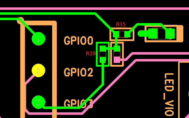
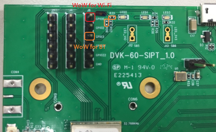
Wow location for Wi-Fi and BT on the 60-SIPT DVK
60-2230C Development Kit v1.0
- Wi-Fi WoW – This pin can be probed at TP4 without any modification of the development kit.
- Bluetooth WoW – There is currently no pinout for this pin. It will be added in the next generation of the development kit (v1.1).
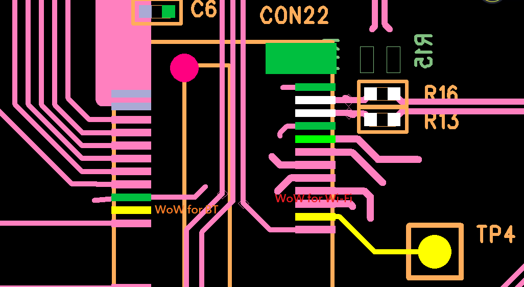
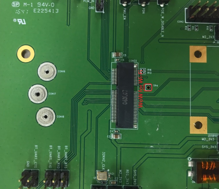
Wow location for Wi-Fi and BT on the 60-2230C DVK
Software
This section describes all software related requirements for Wake on Wireless to work with the 60 Series radios. All WoW signals emanating from the SIP are active low, and for Wi-Fi the pin assertion will last for approximately 1 second before reverting to its normal state.
The 60 Series host software supports the following bus interfaces:
| Interface | Wi-Fi | Bluetooth | Note |
|---|---|---|---|
| SDIO | x | x | |
| PCIE | |||
| USB | x | ||
| UART | x |
Host Requirements
In order for WoW to function properly, the host system must be able to maintain power to radio when the host processor is suspended.
The 60 series Wi-Fi driver will check that the SDIO host controller has the MMC_PM_KEEP_POWER capability set. If not set the radio driver will not report support for WoW, and will fail all suspend requests or attempts to set a WoW trigger.
Wi-Fi Configuration
802.11 Netlink
The following netlink 802.11 WoW triggers are supported. These triggers may be configured at any time, however the 60 series Wi-Fi radio driver will only enable the trigger when it is notified that the host is actually suspending. Consequently one can’t simply configure a WoW trigger and expect the radio to assert the GPIO line when the trigger condition is met (e.g. disconnect) because the trigger may not be enabled.
- NL80211_WOWLAN_TRIG_DISCONNECT - Loss of beacons
- NL80211_WOWLAN_TRIG_ANY - Loss of beacons or RX of any unicast 802.11 packet
- NL80211_WOWLAN_TRIG_NET_DETECT - Network detection
Note NL80211_WOWLAN_TRIG_NET_DETECT supports the full channel set, but only a single SSID, and no 'Match' support.
iw
The iw cli configuration utility may be used to display and change parameters of network interfaces that are specific to wireless operation. One may use iw to check for WoW support and to configure WoW parameters for the 802.11 radio.
To check Wi-Fi radio WoW support, use the following command:
iw phy0 info ... WoWLAN support: * wake up on anything (device continues operating normally) * wake up on disconnect * wake up on network detection, up to 0 match sets ...If radio is associated before host is suspended, the following iw command may be used to wake the host if the connection is lost:
iw phy0 wowlan enable disconnectIf radio is associated before host is suspended, the following iw command may be used to wake the host if the connection is lost or an 802.11 unicast packet is received:
iw phy0 wowlan enable anyIf radio is not associated before host is suspended, the following iw command may be used to wake the host when the network becomes available:
iw phy0 wowlan enable net-detect interval 5000 freqs 2412 5180 active ssid foobarNote The interval is required to complete the NL80211_WOWLAN_TRIG_NET_DETECT request, but is not used as the scan interval by the radio.
Events
The following events are sent by the 60 series Wi-Fi radio driver in response to a WoW trigger occurrence.
- NL80211_WOWLAN_TRIG_WAKEUP_PKT_80211 - RX of a unicast packet
- NL80211_WOWLAN_TRIG_NET_DETECT_RESULT - Network detected
- NL80211_WOWLAN_TRIG_DISCONNECT - Loss of beacons
BT Configuration
The following HCI Command is used to configure the GPIO that is used to wake the host.
hcitool cmd <OGF> <OCF> <WAKEUP METHOD> <GAP VALUE>| Param | Value |
|---|---|
| OGF | 0x3F |
| OCF | 0x53 for UART, 0x59 for USB |
| WAKEUP METHOD | 0x01 to 0xFE = GPIO number |
| GAP VALUE | Time of GPIO pull-down, Default = 0x64 (100ms) |
BT Uart:
hcitool -i hci0 cmd 0x3F 0x53 0x03 0x03 0x01 0xFFBT Usb:
hcitool -i hci0 cmd 0x3F 0x59 0x03 0x03Adaptive World Mode
60-SIPT/60-2230C
Introduction
This application note provides information on the Adaptive World Mode (AWM) feature for the 60 series 60-SIPT and 60-2230C products.
When the radio's regulatory domain is configured for World Mode, this feature uses an FCC-compliant geo-location algorithm and the 802.11d Country IE to determine the current location and set the regulatory country code of the client radio for optimal performance.
Components
AWM consists of 4 main components - the driver, radio firmware, adaptive world mode daemon and database, and the Linux CRDA database. These components must be properly deployed by the customer for this feature to work correctly and maintain regulatory compliance. The following sections describe these components, their requirements, and how they interact to optimize the radio's performance.
Driver
The Ezurio Wi-Fi driver facilitates secure passage of information between the AWM daemon and radio firmware. In addition, it monitors the radio operation to ensure that the geo-location is updated in a timely manner without errors, and it coordinates the regulatory country settings used by the firmware and the Linux Wi-Fi radio stack. If any anomaly is detected the driver resets the radio stack back to its initial world mode boot settings.
Radio Firmware
The radio firmware receives messages from the AWM daemon, decrypts and validates that the message is not a replay or been tampered with, and adjusts the radio's hardware registers and TX powers to maintain regulatory compliance. In addition, the firmware maintains a 60-minute timer which resets each time AWM "checks in". If this timer should ever expire the firmware informs the driver and reverts to its boot time world mode settings.
Linux CRDA Database
The Linux CRDA component is a historical daemon used to look up the regulatory country code settings from an external database (CRDA database) and send them to the Linux Wi-Fi radio stack for use in determining the valid channel set and per channel characteristics (e.g. DFS, passive scan, allowed bandwidth, etc.) for a given regulatory country code/domain.
Prior to kernel 4.15 the Summit backports package compiled this database directly into the Linux Wi-Fi stack, but since 4.15 both CRDA and the ability to statically compile in the database have been deprecated. Instead, the Linux community has chosen to update the database format and have it read in directly by the Linux Wi-Fi stack. The name and path of this database is /lib/firmware/regulatory.db.
When this feature is enabled, upon boot the Linux Wi-Fi radio stack reads this database to obtain the list of valid countries/domains and associated data. In addition, the database is referenced each time the Linux Wi-Fi stack is provided a location hint via the associated AP's 802.11d country IE, a driver notification, or a user notification.
In order to meet regulatory compliance the CRDA feature, which is controlled by the CFG80211_CRDA_SUPPORT kernel configuration option, MUST be enabled in the host's Linux kernel build and an appropriate regulatory.db MUST be deployed. Ezurio provides such a regulatory.db in each radio firmware package it releases.
Note: Deployments using kernel 4.4 or newer do not need to configure CFG80211_CRDA_SUPPORT, however the regulatory.db still needs to be present.
Adaptive World Mode
Overview
The adaptive world mode daemon (AWM) is a user mode application responsible for implementing the geo-location algorithm. Like CRDA, it makes use of a cryptographically signed database, /lib/firmware/lrdmwl/regpwr.db, containing the list of 802.11d country codes, per country hardware power limitations, and channel characteristics required by the radio firmware to stay in regulatory compliance for a given location/country. If this database is not present or has been tampered with, AWM will not perform geo-location detection and thus the radio stack will stay in its sub-optimal boot time world mode state.
When AWM starts it verifies that the RegulatoryPwrDB exists, that it was signed with a certificate created by Ezurio and its content has not been tampered with. Afterwards it enumerates the interfaces on the system looking for wireless adapters which indicate they are Ezurio Radios, have a station/managed or AP interface, and whose OTP memory is set to the worldwide (WW) regulatory domain.
For each adapter meeting this criteria AWM stores this information and then waits for one of these adapters to indicate its interface is up if it is not already up. Once AWM finds such an interface, it marks the interface the active interface and initiates a geo-location scan to determine the present location. Upon scan completion AWM sorts the 802.11d IEs broadcast by the surrounding APs according to RSSI value. If the location can be determined and the geo-location is found in the RegulatoryPwrDB, AWM sends the corresponding RegulatoryPwrDB entry to the driver/firmware for further processing and optimization.
If at any point AWM receives an indication that the active interface is removed or marked down, AWM may re-enumerate the system adapters looking for another Ezurio Radio and when found restart a geo-location scan. Finally, in cases where AWM is stopped it informs the radio firmware to revert to its world mode domain settings before exiting.
Interface Selection
While AWM manages multiple Wi-Fi adapters, it uses a single interface for geo-location detection. The selection algorithm uses the first interface it finds that matches the preferred interface type, by default a managed/station interface, and is up and capable of issuing scans. When searching for a preferred interface to use, the selection algorithm starts with the lowest numbered Wi-Fi adapter (e.g. phy0) and lowest numbered interface index (e.g. wlan0) it can. If the preferred interface type can't be found AWM uses a non-preferred interface.
Once a usable interface is found AWM uses this interface for all geo-location scans until such time that the interface is no longer available (e.g. interface is set down or removed) unless the useable interface is not of the preferred type, in which case AWM will re-evaluate the available interfaces whenever a new interface arrives. Should AWM switch the active interface or adapter, it may initiate a geo-location scan depending on its operating mode.
The preferred interface type may be changed by using the command line option -F with one of the following values:
| Value | Behavior |
|---|---|
| STA | Prefer station/managed interfaces for geo-location scans (default) |
| AP | Prefer AP interfaces for geo-location scans |
| NONE | No preference, use the first interface found for geo-location scans |
Algorithm
The AWM geo-location algorithm maintains up to 5 APs in its country code list, with the AP with the highest RSSI ranked first. The daemon then acts based on the following rules:
| APs Detected | Total Count Country Code A | Total Count Country Code B | Action |
|---|---|---|---|
| >=3 | 3 of top 5 APs | 2 | Set Regulatory Domain to Country Code A |
| >=3 | 2 of top 5 APs | 2 | Remain in Worldwide Mode |
| >=3 | 2 of top 5 APs | 1 | Set Regulatory Domain to Country Code A |
| >=3 | 1 of top 5 APs | 1 | Remain in Worldwide Mode |
| 2 | 2 of top 2 APs | 0 | Set Regulatory Domain to Country Code A |
| 2 | 1 of top 2 APs | 1 | Remain in Worldwide Mode |
| <=1 | 1 of top 1 APs | 0 | Remain in Worldwide Mode * |
*AWM lite mode will Set Regulatory Domain to Country Code A
Note: The adaptive world mode daemon only works with Ezurio 60 series radios.
Opportunistic Scans
AWM may make use of scan results that were initiated by ‘3rd Party’ applications, e.g. wpa supplicant, to determine its geo-location. By doing so it results in fewer interruptions to the Wi-Fi stack and thus better overall network performance.
Standard Mode
Standard mode operation is the out-of-box operating mode and is compliant with FCC regulatory requirements. Under normal operation once AWM sends the geo-location to the radio firmware it starts a periodic 30-minute timer, unless it fails to negotiate a country code in which case the timer may be set to expire sooner, which upon expiration causes AWM to revalidate its current geo-location. When running in standard mode, every time an interface change occurs AWM will initiate a geo-location scan in order to comply with the FCC requirement that ‘Device must recheck the geo-location at least once every hour, when the device is switched on and connections are established or changed’.
Lite Mode
Lite mode is an operating mode that allows operating in a manner which is not FCC compliant but is less disruptive to the overall system, e.g. no geo-location check every hour, and still allows detection of current geo-location. When operating in lite mode AWM continues its current boot procedure where it enumerates the adapters and initiates a geo-location scan to determine the present location. However, once the geo-location is determined and AWM has sent this information to the radio firmware, it stops all future geo-location scans. Unlike standard mode, as interfaces come and go, AWM will transition across them without initiating a geo-location scan unless AWM is transitioning from having no useable interface in which case it will restart the full geo-location detection algorithm. When running in this mode, forcing AWM to transition from this no useable interface state (e.g. set all interfaces down via ip link set wlan0 down) is one way to force AWM to re-evaluate its geo-location.
To enable lite mode use the command line option -M and the value lite.
Note: Devices running with AWM in lite mode are not FCC compliant and must not be shipped to the USA.
Strict Country Enforcement
AWM’s lite mode is only intended to be used exclusively outside countries that require the geo-location be checked periodically, e.g. USA. Therefore, to stay compliant and help enforce the use of AWM’s standard operating mode where required, whenever AWM determines the geo-location is in one of these countries while running in lite mode, AWM will stay in world mode and immediately stop all further active geo-location scan attempts. Once AWM is in this state the only way to leave this state is to reboot the device, set all interfaces down/up, or AWM making use of an opportunistic scan to determine that the geo-location is no longer in an area where strict country enforcement is required.
Wi-Fi MAC Address Overrides
AWM uses the OUI assigned to the Wi-Fi MAC address to determine if AWM should manage the regulatory domain for a wireless radio. The OUI that AWM uses for this defaults to CCEE40.
If the user overrides this MAC address with another address, then AWM will no longer manage the radio's regulatory domain unless the new OUI is provided, which can be done using the -O [OUI] parameter when starting AWM.
Note: Releases 11.39.0.19 and newer no longer use the OUI to determine if the radio is manageable.
Installation
This section lists the components and tools needed to deploy adaptive world mode feature on an end device.
Software Components
The AWM feature is made available as a binary executable and supporting files. These files are distributed as a tarball package having the name:
adaptive_ww-<openssl_version>-<platform_ext>-<version>.tar.bz2The list of supported platforms and platform naming conventions are:
| Platform | Platform Extension Name |
|---|---|
| arm soft-float | arm-eabi |
| arm hard-float | arm-eabihf |
| arm aarch64 | arm-eabiaarch64 |
| x86 32-bit | x86 |
| x86 64-bit | x86-64 |
| PowerPC 32-bit | powerpc-e5500 |
The files in the tarball are listed below along with a description and location where they should be installed on the end device. They must be present and/or running on the end device for AWM to work properly.
| File | Description | Location |
|---|---|---|
| regulatory.db | The CRDA database | /lib/firmware |
| regpwr.db | The AWM database | /lib/firmware/lrdmwl |
| adaptive_ww | The AWM daemon | /usr/bin |
| adaptive_ww | system V service file | /etc/init.d/ |
| adaptive_ww.services | systemd service file | /usr/lib/systemd/system/ |
Note: The first release of AWM named the system V service file S30adaptive-ww. It will be changed to adaptive_ww in subsequent releases.
Shared Object Dependencies
The adaptive_ww daemon depends on the following shared objects:
- libnl-genl-3.so.200
- libnl-route-3.so.200
- libnl-3.so.200
- libcrypto.so.1.1 or libcrypto.so.1.0.0
- libpthread.so.0
- libc.so.6
Lightweight Manufacturing Utility
The LMU vendor tool is used to set the radio's OTP memory to the regulatory country code into which the device is shipping. If world mode is desired the vendor should use WW or WW440 where the 440 indicates that the radio has been certified for EN 300-440 compliance and as such may use U-NII-3 band (5725-5850) when determined to be in an ETSI country. More information about this tool may be found in the 60 series vendor tool app note document.
Note: By default Ezurio radios are set to WW in the factory.