/filters:background_color(white)/2024-10/Nitrogen 8M Mini SMARC1.267 without wireless.png)
/filters:background_color(white)/2024-06/SMARC_CAR%20Kit.png)
Getting Started
This guide explains how to quickly get up and running with Ezurio's Nitrogen8M Mini SMARC Module and Universal SMARC Carrier Board. Please note that the two items are sold separately and are not available as a bundled EVK.
What You Will Need
- 1x Nitrogen8M Mini SMARC Module, #P/N starting with: 8MM_SMARC_SOM*.
- (Recommended): 1x Universal SMARC Heatsink (#P/N 450-00238).
1x Universal SMARC Carrier Board (#P/N SMARC_CAR), which includes:
- 4x Mounting Screws.
- 1x Power Supply (5V@3A).
- 1x Serial Cable.
- Antenna(s).
On the Board
The following sections identify and highlight the key components and interfaces of the Nitrogen8M Mini SMARC Module and Universal SMARC Carrier Board:
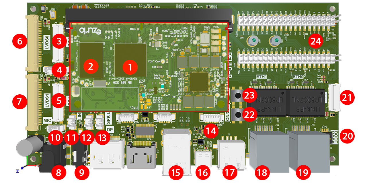
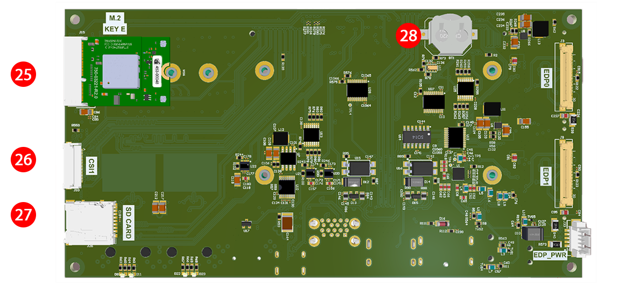
| No. | Component / Interface | Location |
|---|---|---|
| 1 | Nitrogen8M Mini SMARC Module | SOM |
| 2 | Boot Mode Switch for BOOT_MODE[0] (SW1) | SOM |
| 3 | MIPI-DSI0 Display Connector (J13) | Carrier Board |
| 4 | LVDS I2C Touch Connector (J23) | Carrier Board |
| 5 | MIPI-DSI1 Display Connector (J14) | Carrier Board |
| 6 | LVDS0 Display Connector (J21) | Carrier Board |
| 7 | LVDS1 Display Connector (J22) | Carrier Board |
| 8 | Barrel Jack Power Connector (J17) | Carrier Board |
| 9 | 3.5 mm Audio Jack (J4) | Carrier Board |
| 10 | 3-Pin Molex Microphone Connector (J8) | Carrier Board |
| 11 | 2-Pin Molex Line-In Connector (J6) | Carrier Board |
| 12 | 2-Pin Molex Right Speaker Connector (J7) | Carrier Board |
| 13 | 2-Pin Molex Left Speaker Connector (J5) | Carrier Board |
| 14 | 6-Pin Molex Serial Debug Connector for A53 and M4 Core Console Access (J18) | Carrier Board |
| 15 | 2x USB 3.1 Gen 1 Type-A Ports (J24) | Carrier Board |
| 16 | USB Type-C OTG Port (J25) | Carrier Board |
| 17 | USB 2.0 Type-A Port (J2) | Carrier Board |
| 18 | Gigabit Ethernet 1 Connector (J32) | Carrier Board |
| 19 | Gigabit Ethernet 0 Connector (J31) | Carrier Board |
| 20 | Boot Mode Switches for BOOT_MODE[3:1] (S1) | Carrier Board |
| 21 | MIPI-CSI0 Camera Connector (J11) | Carrier Board |
| 22 | On/Off Switch (SW2) | Carrier Board |
| 23 | Reset Switch (SW1) | Carrier Board |
| 24 | 2x Expansion Connectors for GPIO, UART, SPI, I2S, and I2C (J27 + J28) | Carrier Board |
| 25 | M.2 PCIe Connector (J15) | Carrier Board |
| 26 | MIPI-CSI1 Camera Connector (J10) | Carrier Board |
| 27 | microSD Card Slot (J26) | Carrier Board |
| 28 | RTC Battery (BT1) | Carrier Board |
Info: Please be advised that interfaces or features not listed here are not supported by the SOM due to hardware limitations of the CPU, regardless of whether they are physically exposed or accessible through the Universal SMARC Carrier Board.
Boot Modes
Two switches govern boot mode selection: SW1 on the Nitrogen8M Mini SMARC Module and S1 on the Universal SMARC Carrier Board, indicated as №2 and № 20 respectively in the diagram above. The boot medium is then determined by their combined binary switch pattern. Note: The Universal SMARC Carrier Board switch polarity was reversed between REV10 and REV20 — the switch positions are inverted, but the signal levels remain the same. See the tables below for more details.
REV20+
| Boot Selection | S1 Switch 3 BOOT_MODE[3] | S1 Switch 2 BOOT_MODE[2] | S1 Switch 1 BOOT_MODE[1] | SW1 BOOT_MODE[0] | Binary Pattern BOOT_MODE[3:0] |
|---|---|---|---|---|---|
| Location | Universal SMARC Carrier Board | Universal SMARC Carrier Board | Universal SMARC Carrier Board | Nitrogen8M Mini SMARC Module | |
| Boot From Internal Fuses | Don't Care | Don't Care | OFF (0) | OFF (0) | 0000 |
| Serial Downloader (USB) | Don't Care | Don't Care | OFF (0) | ON (1) | 0001 |
| eMMC (uSDHC1) | Don't Care | Don't Care | ON (1) | OFF (0) | 0010 |
| Reserved | N/A | N/A | ON (1) | ON (1) | 0011 |
| SD Card (uSDHC2) | N/A | N/A | N/A | N/A | N/A |
REV10
| Boot Selection | S1 Switch 3 BOOT_MODE[3] | S1 Switch 2 BOOT_MODE[2] | S1 Switch 1 BOOT_MODE[1] | SW1 BOOT_MODE[0] | Binary Pattern BOOT_MODE[3:0] |
|---|---|---|---|---|---|
| Location | Universal SMARC Carrier Board | Universal SMARC Carrier Board | Universal SMARC Carrier Board | Nitrogen8M Mini SMARC Module | |
| Boot From Internal Fuses | Don't Care | Don't Care | ON (1) | OFF (0) | 0000 |
| Serial Downloader (USB) | Don't Care | Don't Care | ON (1) | ON (1) | 0001 |
| eMMC (uSDHC1) | Don't Care | Don't Care | OFF (0) | OFF (0) | 0010 |
| Reserved | N/A | N/A | OFF (0) | ON (1) | 0011 |
| SD Card (uSDHC2) | N/A | N/A | N/A | N/A | N/A |
Board Assembly
Warning: Always ensure the board is completely powered off and disconnected from any power source before making any changes. Assembling or modifying the hardware while powered may cause irreversible damage.
To assemble the Nitrogen8M Mini SMARC Module and Universal SMARC Carrier Board, follow the steps below:
- Insert the Nitrogen8M Mini SMARC Module into J1 on the Universal SMARC Carrier Board and secure it in place using the provided mounting screws.
- Recommended: Attach the Universal SMARC Heatsink to the Nitrogen8M Mini SMARC Module using the spring-pin connectors. Available as an optional accessory.
- Optional: Also, if your Nitrogen8M Mini SMARC Module includes wireless connectivity, ensure the antenna is securely connected, as it may be needed in later steps.
Serial Console for Terminal and Debug Access
To set up a serial connection, connect the DB9 end of the serial cable included with the kit to the J18 / SERIAL header on the Universal SMARC Carrier Board, and the CONSOLE end to your host PC via a 5V USB-to-Serial adapter, which is not included by default. We recommend and have tested the Tripp Lite Keyspan USA-19HS.
On Linux, rundmesg | grep -E 'ttyUSB|ttyACM' to find the serial device (typically /dev/ttyUSB0 or /dev/ttyACM0), then connect using screen /dev/ttyUSB0 115200. Minicom and Picocom are common alternatives. If needed, add your user to the dialout group with sudo usermod -a -G dialout $USER, then log out and back in for the change to take effect. On Windows, open Device Manager, find the COM port under Ports (COM & LPT), and connect using PuTTY, TeraTerm, RealTerm, or Serial Debug Assistant. The default serial settings are 115200 baud, 8N1.Building an Image
Follow the image build instructions from the EZ BSP Guide:
User Guide - EZ BSP for Nitrogen8M Mini (Coming Soon)
Programming uSD Card
Not supported.
Programming eMMC
Follow the flashing instructions from the EZ BSP Guide:
User Guide - EZ BSP for Nitrogen8M Mini (Coming Soon)
Additional Resources
Additional resources can be found in the Nitrogen8M Mini support page:
https://www.ezurio.com/support/series/nitrogen8m-mini-smarc