
Introduction
Overview
This document describes key hardware aspects of the mFlexPIFA. This document is intended to assist device manufacturers and related parties with the integration of this radio into their host devices. Data in this document is drawn from several sources. For full documentation on the mFlexPIFA, visit:
General Description
This datasheet is subject to change. Please contact Ezurio for further information.
Features & Benefits
The mFlexPIFA device features and benefits are described in the following table.
- Designed to be installed directly on metal
- Can be installed on different conductive surfaces and thicknesses
- Can be installed on flat or curved surfaces
- Quick and easy Installation
- Adhesive holds to surface during humidity exposure and hot/cold cycles
- RoHS compliant
Specification Summary
Table: mFlexPIFA specifications
| Specification | Value |
|---|---|
| Peak Gain | +2 dBi |
| Average Gain | >-4.2 dBi |
| Impedance | 50 ohms |
| Type | Flexible Planar Inverted F Antenna (FlexPIFA) |
| Polarization | Linear |
| VSWR | ≤ 3.0:1, 2400 - 2480 MHz |
| Frequency | 2400 - 2480 MHz |
| Weight | 1.8 g |
| Size | 25.4 mm × 23.4 mm × 2.5 mm |
| Antenna Color | Clear Yellow |
| Adhesive | 3M 100MP |
| Operating Temp | -40°C to +85°C |
| Connector Height | U.FL: 2.5 mm maximum |
| Connector Height | MHF4L: 1.7 mm maximum |
Environmental
| Feature | Description |
|---|---|
| Lead Free | Lead-free and RoHS Compliant |
Warranty
| Feature | Description |
|---|---|
| Warranty Terms | One Year Warranty |
Hardware Architecture
Mechanical Drawings
Physical Dimensions
001-0030
Note: All measurements are in millimetres (mm).
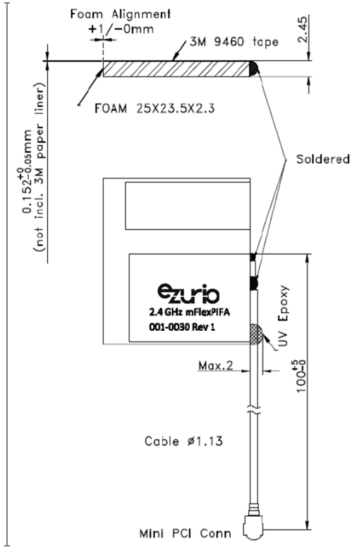
Figure: Physical dimensions
Integration Guidelines
Antenna Characteristics
Test Setup
Antenna measurements such as VSWR are measured with an Agilent E5071C Vector Network Analyzer. Radiation patterns are measured with a CMT Planar 804/1 Vector Network Analyzer in a Howland Company 3100 Chamber equivalent. Phase Center is 9 inches above the Phi positioner.
Flat surface measurements are done with the antenna centered on a 100 x 100 mm, 0.35 mm thick brass plate. Curved surface measurements are taken by placing the antenna on a curved surface made of 0.35 mm thick brass.
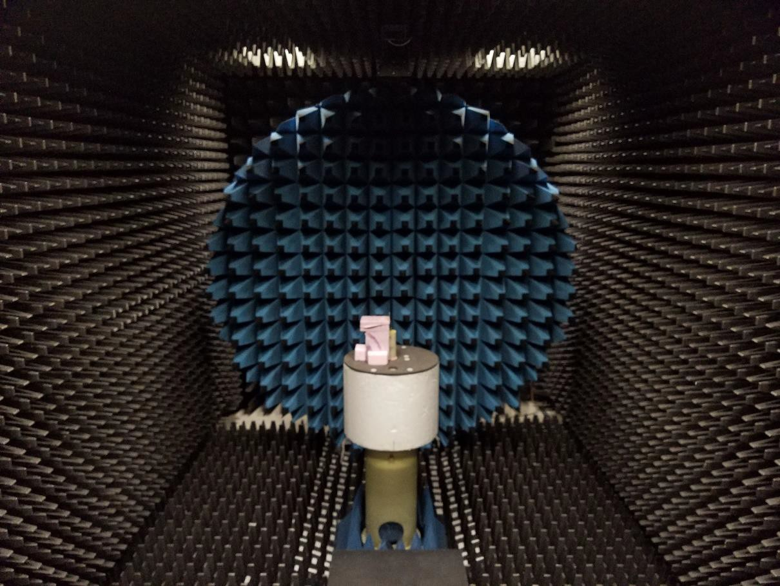
Figure: Antenna Chamber
Flat Surface Antenna Measurements
Return Loss
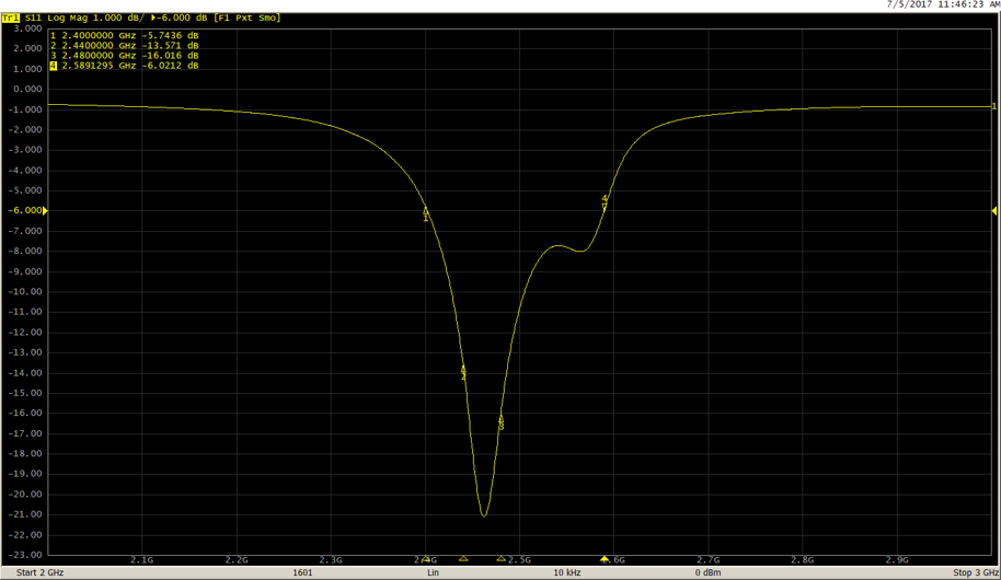
Figure: Return loss measured on a 0.35 mm thick, 100 x 100 mm brass plate
Flat Surface Antenna Radiation Performance
Antenna Setup
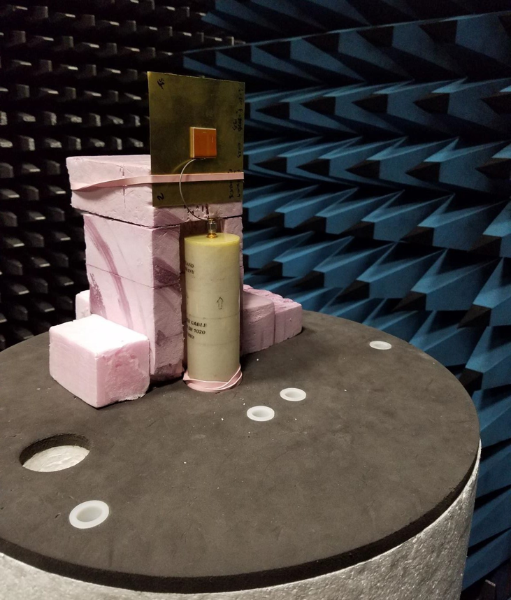
Figure: Flat surface setup
Results – Flat Surface
2400 MHz
Azimuthal Conical Cuts at 2400 MHz
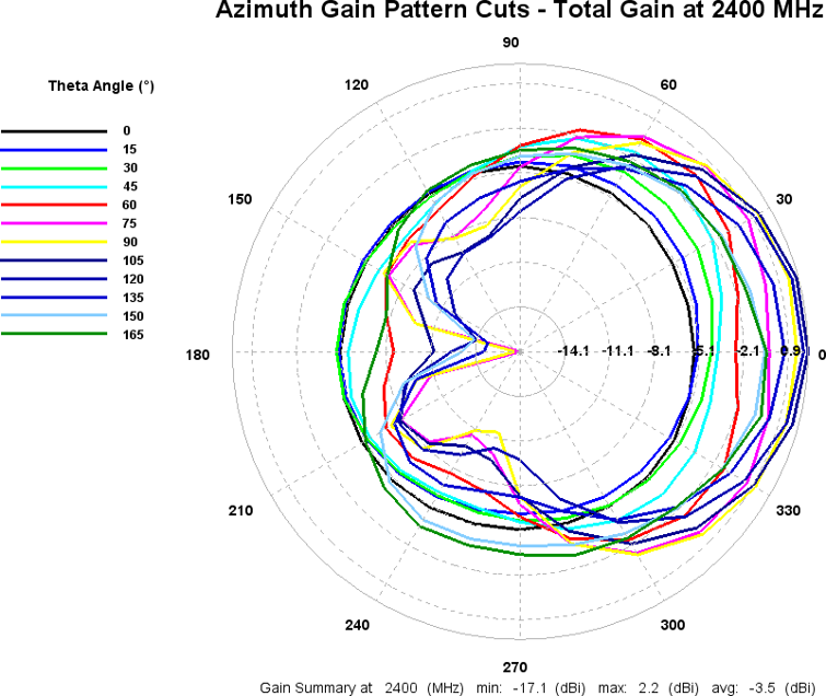
Figure: Total gain pattern – 2400 MHz
3D Plots at 2400 MHz
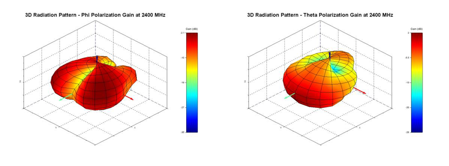
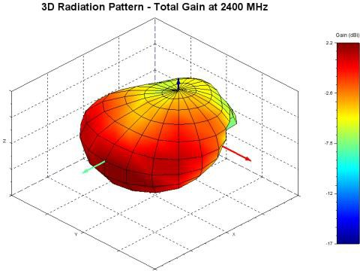
Figure: Phi, theta, and total gain plots – 2400 MHz
2440 MHz
Azimuthal Conical Cuts at 2440 MHz
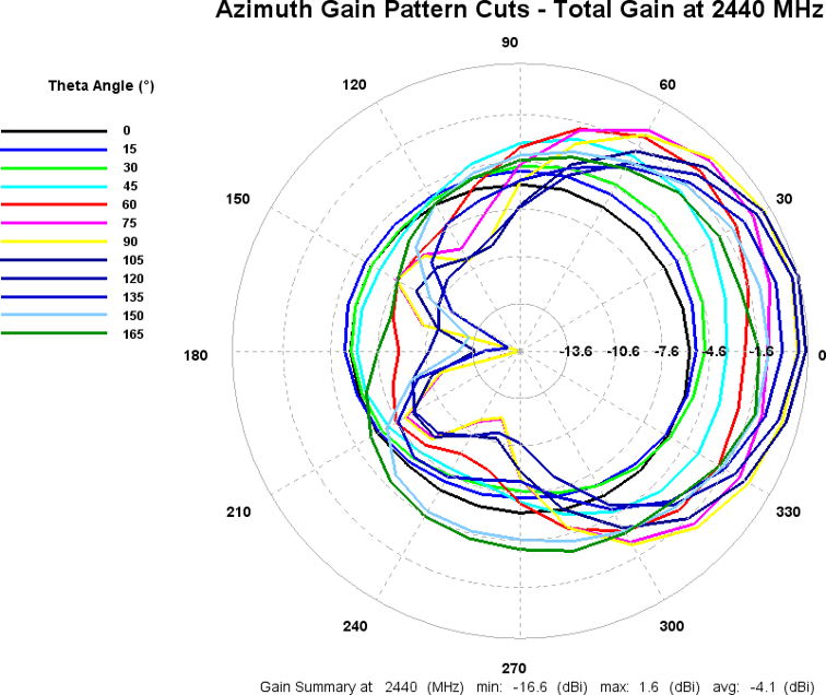
Figure: Total gain pattern – 2440 MHz
3D Plots at 2440 MHz
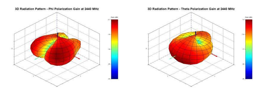
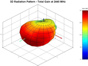
Figure: Phi, theta, and total gain plots – 2440 MHz
2480 MHz
Azimuthal Conical Cuts at 2480 MHz
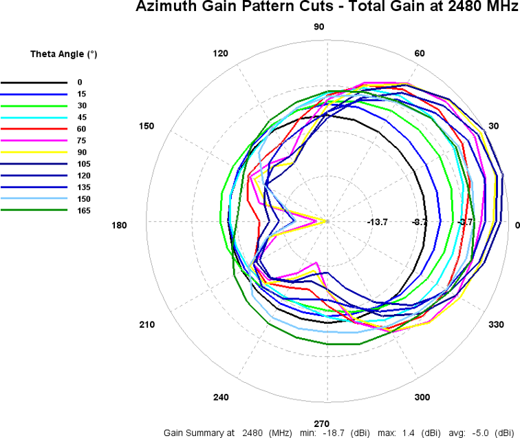
Figure: Total gain pattern – 2480 MHz
3D Plots at 2480 MHz
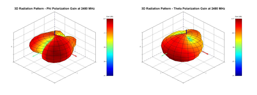
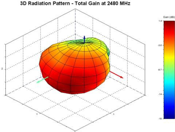
Figure: Phi, theta, and total gain plots – 2480 MHz
Curved Surface Antenna Radiation Performance
Antenna Setup
The mFlexPIFA is placed on the outside of a 60-mm outer diameter metal tube.
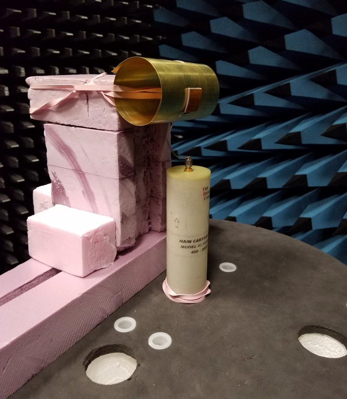
Figure: Convex curve setup
Results – Curved Surface
2440 MHz
Azimuthal Conical Cuts at 2440 MHz
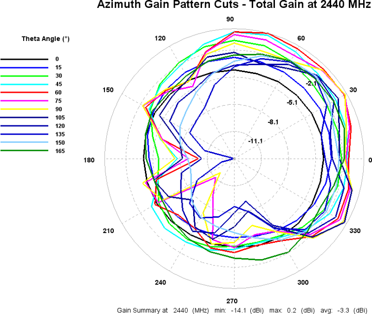
Figure: Total gain pattern – 2440 MHz
3D Plots at 2440 MHz
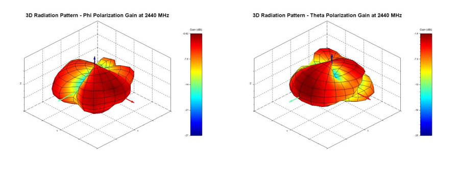
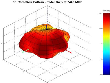
Figure: Phi, theta, and total gain plots – 2440 MHz
Optimal Installation Guide
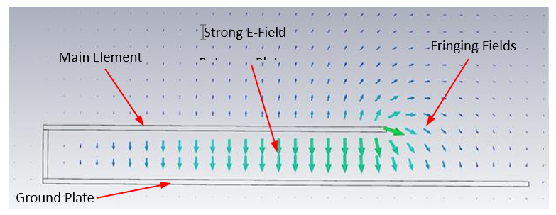
Figure: E-field radiation from the FlexPIFA. Taken from CST simulation
Keep the main element clear of any non-metal objects (such as plastics) on top of it by at least three millimeters (see Top clearance).
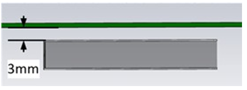
Figure: Top clearance
Similarly, keep the two long sides of the mFlexPIFA clear of any non-metal objects by at least two millimeters (see Non-metal side clearance (Top View)). For metal objects, the top side of the mFlex should be kept clear by at least two millimeters and the bottom side of the mFlex at least 12 millimeters (see Metal side clearance (Top View)). Images below are based on the 2.4GHz FlexPIFA (Ezurio PN: 001-0014) and used for reference only.
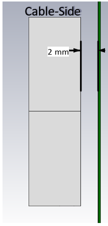
Figure: Non-metal side clearance (Top View)
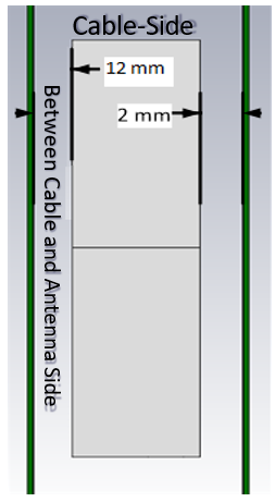
Figure: Metal side clearance (Top View)
A one-millimeter clearance should be observed from the ground wall to any non-metal object (Non-metal ground wall clearance). A 15-millimeter clearance should be observed for metal objects (Metal ground wall clearance).
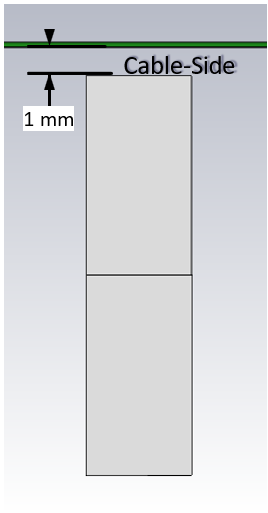
Figure: Non-metal ground wall clearance
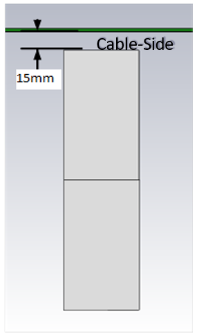
Figure: Metal ground wall clearance
Important! Mounting the mFlexPIFA in a situation that does not allow for these clearance recommendations may change the gain characteristics stated in the datasheet, which could impact overall range of the wireless system.
The ideal material for the mFlexPIFA to be mounted on (for maximum performance) is brass. However, as previously mentioned, the mFlexPIFA can tolerate other metallic surfaces and thicknesses and still radiate effectively. Depending on the type of material, the mFlexPIFA may be detuned.
The coaxial cable feeding the mFlexPIFA should be routed away from the antenna. Do not run the coaxial cable over the top of the mFlexPIFA or near the tip of the main element. The cable should be routed perpendicular to the side of the mFlexPIFA (this is the way the cable comes assembled) or away from the ground wall. These options are shown in Recommended cable routing.
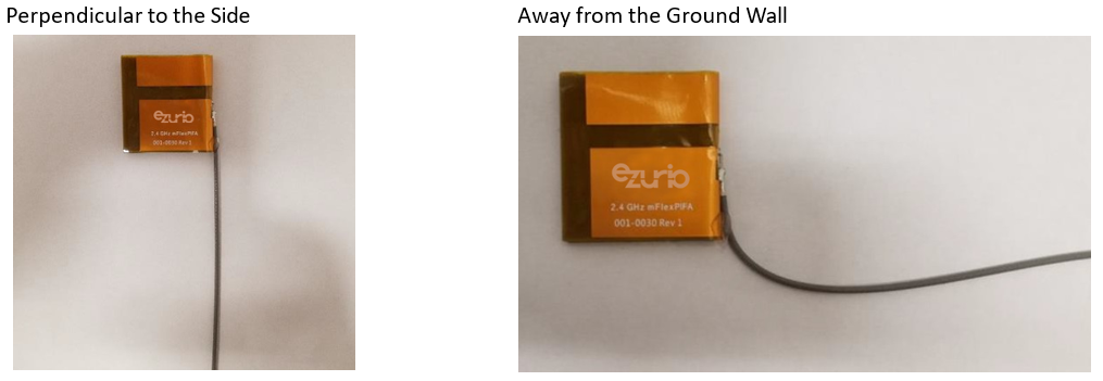
Figure: Recommended cable routing
As with any antenna, do not place objects near the antenna (except as described in the next section). Other objects, such as an LCD display, placed near the antenna may not affect its tuning but can distort the radiation pattern. Materials that absorb electromagnetic fields should be kept away from the antenna to maximize performance.
The following are some common things to keep in mind when placing the antenna:
- Wire routing
- Speakers – These generate magnetic fields Battery location
- Proximity to human body
- Display screen – These absorb radiation
Flex Limits of the mFlexPIFA
One of the unique features of the mFlexPIFA is its ability to flex. However, due to the adhesive, there are limits to how much the antenna can be flexed and still remain secured to the device. The mFlexPIFA should not be flexed in a convex position with a radius less than 60 millimeters. Going smaller than this may result in the antenna peeling off the surface over time. Should a tighter radius of curvature be required, we recommend that you contact Ezurio for assistance.
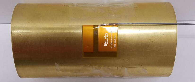
Figure: Convex mounted
We do not recommend mounting the mFlexPIFA in a metal-enclosed concave position. In this scenario, the limiting factor is performance. The ground plate of the antenna is pressed closer to the main element. The fringing fields developing off the end of the element are responsible for most of the radiation. In a concave position, the fringing fields are adversely affected, and gain suffers. This can also potentially create a Faraday’s cage and cancel most of the RF radiation from the antenna.
If a concave position is required, we recommend that you contact Ezurio for assistance.
Note: The mFlexPIFA is not designed to be twisted or crumpled. The adhesive back should lay flush with the surface on which it is mounted.
Ordering Information
Table: Ordering information
| Order Number | Description |
|---|---|
| 001-0030 | mFlexPIFA – 2.4 GHz embedded metal FlexPIFA antenna, 100 mm cable length w/ U.FL connector |
| EFA2400A3S-10MH4L | mFlexPIFA – 2.4 GHz embedded metal FlexPIFA antenna, 100 mm cable length w/MHF4L connector |
Additional Support & Appendices
Additional Information
Please contact your local sales representative or our support team for further assistance:
| Headquarters | Ezurio 388 South Main Street, Suite 330 Akron, OH 44311 USA |
| Website | http://www.ezurio.com |
| Technical Support | http://www.ezurio.com/resources/support |
| Sales Contact | http://www.ezurio.com/contact |
Note: Information contained in this document is subject to change.
Ezurio’s products are subject to standard Terms & Conditions.
| © Copyright 2026 Ezurio. All Rights Reserved. Any information furnished by Ezurio and its agents is believed to be accurate but cannot be guaranteed. All specifications are subject to change without notice. Responsibility for the use and application of Ezurio materials or products rests with the end user since Ezurio and its agents cannot be aware of all potential uses. Ezurio makes no warranties as to non-infringement nor as to the fitness, merchantability, or sustainability of any Ezurio materials or products for any specific or general uses. Ezurio or any of its affiliates or agents shall not be liable for incidental or consequential damages of any kind. All Ezurio products are sold pursuant to the Ezurio Terms and Conditions of Sale in effect from time to time, a copy of which will be furnished upon request. Nothing herein provides a license under any Ezurio or any third-party intellectual property right. Ezurio and its associated logos are trademarks owned by Ezurio and/or its affiliates. |
Legacy - Revision History
| Version | Date | Notes | Contributors | Approver |
|---|---|---|---|---|
| 2.0 | 15 Aug 2017 | Initial release on website | Sue White | |
| 2.1 | 20 Mar 2018 | Added new antenna connector information; transitioned to new template; updated contact information; updated mounting guidelines | Jay White | |
| 2.2 | 14 Jul 2023 | Updated 2D Antenna Drawing | ||
| 3.0 | 21 Oct 2024 | Ezurio rebranding | Sue White | Dave Drogowski |
| 3.1 | 3 Feb 2025 | Fix antenna images in Optimal Installation Guide | Dave Drogowski | Elaine Baxter |