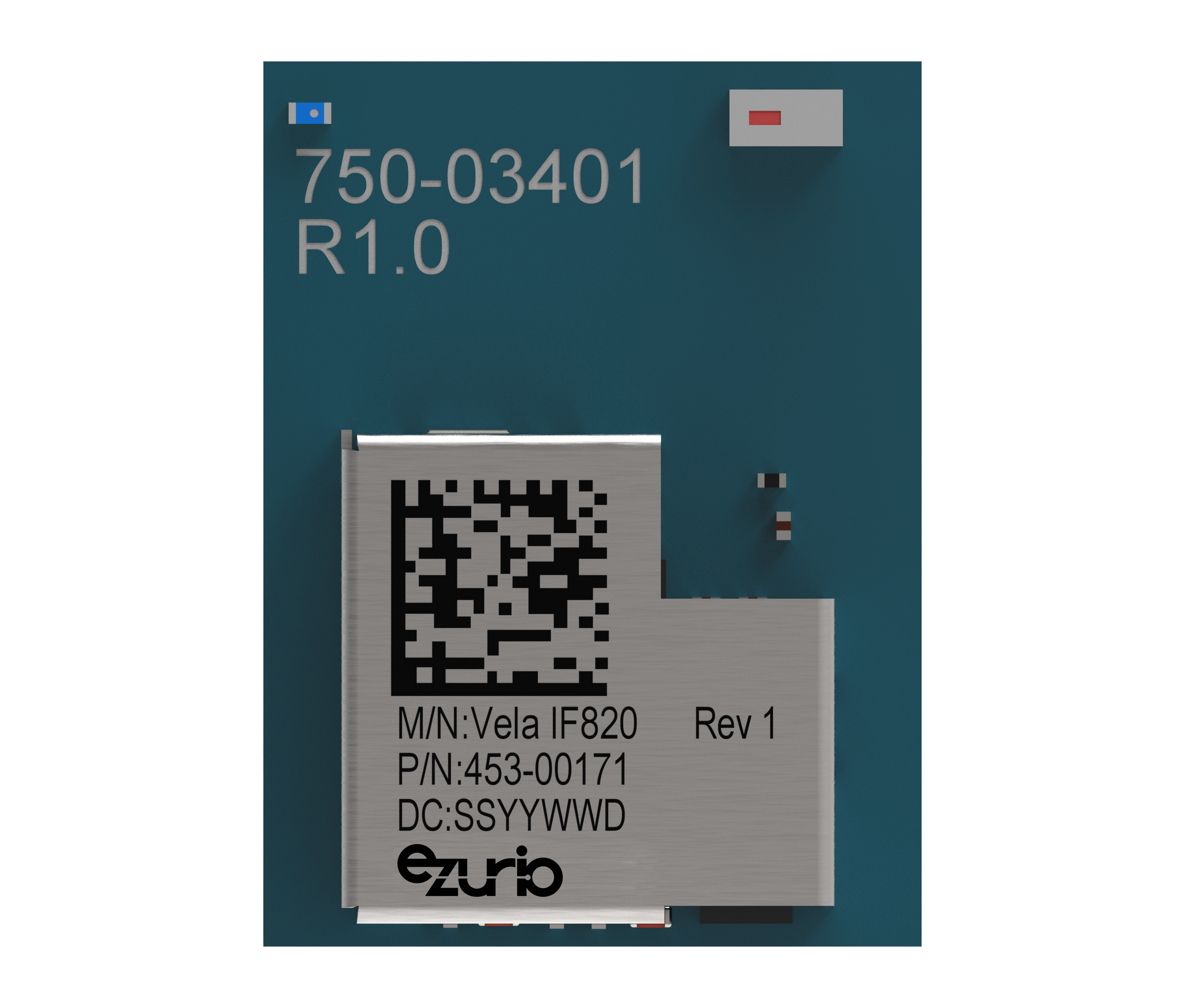
Vela IF820 Series - Bluetooth 5.4 Dual-Mode Modules
Learn more and compare with similar parts on the family page.

Specifications

Antenna Options
Integrated Antenna
Dimension (Height - mm)
2.15 mm
Dimension (Length - mm)
12.5 mm
Dimension (Width - mm)
9.3 mm
Packaging
Tape and Reel
Voltage
2.6 to 3.3 V

Documentation

Name Part Type Last Updated
Product Brief - Vela IF820 Series 453-00171R Product Brief 04/22/2024
Datasheet - Vela IF820 Series 453-00171R Datasheet 11/12/2024

Buy Now

Distributor Part In Stock Region Buy
DigiKey 453-00171R 1851 North America Buy Now
Mouser 453-00171R 991 North America Buy Now
Arrow Electronics 453-00171R 0 North America Buy Now
Avnet 453-00171R 0 North America Buy Now
Future Electronics 453-00171R 0 North America Buy Now


FAQ

How do I flash a Vela IF820 module independent of a DVK using if820_flasher_cli?

Vela IF820 firmware programming is done via the HCI UART.

There are two tools to flash a vela IF820 module detailed in the following link

https://github.com/LairdCP/Vela_IF820_Firmware/releases

if820_flasher_gui is a graphical user interface for flashing Vela IF820 DVKs and dongles, it will auto detect any Vela IF820 DVKs and dongles currently connected to your PC. It cannot be used for flashing a loose module.

if820_flasher_cli is a command line tool for flashing Vela IF820 DVK, dongle and loose modules. Like the GUI it will auto detect a DVK or dongle but you can also specify a com port for a loose module. When specifying a com port the Flasher CLI bypasses the DVK probe auto detect.

When flashing a loose module via a particular com port the following should be noted

  • The following pins are used for flashing firmware BT_UART_TXD, BT_UART_RXD, BT_UART_CTS, BT_UART_RTS
  • Flow control is mandatory 
  • Reset line is also required to be able to enter programming mode
  • UART  settings are 1152008N1
  • CTS needs to be low during a reset to enter programming mode.  On a DVK this is don't via the module recover button but on a loose module the CTS will need to be held low another way.
  • The GUI can only be used to flash DVKs and dongles. You must use the CLI for loose modules. 

You can use the -c option in the IF820 Flasher GUI to specify a com port.

use  the command 

if820_flasher_cli.exe -h

to access the help screen for more details

How do I troubleshoot the Vela IF820 Flasher CLI?

Troubleshooting the IF820 Flasher CLI 

A successful IF820 Flasher CLI session should look something like this, where 20240328_ezserial_app_VELA-IF820-INT-ANT-USB_141616_v1.4.16.16_download.hcd is the file location/name of the firmware image to be flashed.

>if820_flasher_cli.exe -ce -f 20240328_ezserial_app_VELA-IF820-INT-ANT-USB_141616_v1.4.16.16_download.hcd

2024-06-10 15:45:05,617 | INFO | Loading minidriver...

2024-06-10 15:45:07,368 | INFO | Performing chip erase...

2024-06-10 15:45:07,384 | INFO | Chip erase finished

2024-06-10 15:45:07,385 | INFO | Changing baud to 3000000

2024-06-10 15:45:07,395 | INFO | Programming HCD file...

2024-06-10 15:45:13,927 | INFO | Finished programming!


Module not found

The following error is indicative of the module/dongle com port not being found. Double check that the com port of the IF820 is visible.

>if820_flasher_cli.exe -ce -f 20240328_ezserial_app_VELA-IF820-INT-ANT-USB_141616_v1.4.16.16_download.hcd

2024-06-10 15:47:01,707 | ERROR | No boards found

Traceback (most recent call last):

  File "\\Mac\Home\git\vela_if820\Vela_IF820_Firmware\if820_flasher_cli.py", line 78, in

NameError: name 'exit' is not defined

[16908] Failed to execute script 'if820_flasher_cli' due to unhandled exception!


File not found

If you see the following error then the Flasher CLI cannot find  the firmware image.  Double check the spelling of the file name and its absolute path. It may be easiest to ensure the  the firmware image file (.hcd) is in the same folder as the Flasher CLI executable.

>if820_flasher_cli.exe -ce -f 20240328_ezserial_app_VELA-IF820-INT-ANT-USB_141616_v1.4.16.16_download.hcd

2024-06-10 15:51:41,707 | INFO | Loading minidriver...

2024-06-10 15:51:43,426 | INFO | Performing chip erase...

2024-06-10 15:51:43,439 | INFO | Chip erase finished

2024-06-10 15:51:43,440 | INFO | Changing baud to 3000000

2024-06-10 15:51:43,446 | INFO | Programming HCD file...

Traceback (most recent call last):

  File "\\Mac\Home\git\vela_if820\Vela_IF820_Firmware\if820_flasher_cli.py", line 87, in

  File "If820Board.py", line 213, in flash_firmware

  File "HciProgrammer.py", line 110, in program_firmware

FileNotFoundError: [Errno 2] No such file or directory: '20240328_ezserial_app_VELA-IF820-INT-ANT-USB_141616_v1.4.16.16_download.hcd'

[22684] Failed to execute script 'if820_flasher_cli' due to unhandled exception!


Accessing the IF820 Flasher CLI help screen

You can access the help screen with the following command

if820_flasher_cli.exe -h

Which outputs the following

>if820_flasher_cli.exe -h

usage: if820_flasher_cli [-h] [-c CONNECTION] [-ce] [-d] [-f FILE]


CLI tool to flash an IF820 board (or compatible boards) with new firmware.

If no COM port is specified, the tool will automatically detect the board and flash it.

If there is more than one board detected, the user will be prompted to select the board to flash.

The CLI supports chip erase, firmware update, and flashing firmware with chip erase.


options:

  -h, --help            show this help message and exit

  -c CONNECTION, --connection CONNECTION HCI COM port

  -ce, --chip_erase     perform full chip erase.

  -d, --debug           Enable verbose debug messages

  -f FILE, --file FILE  application hex file to flash


Option Descriptions

-c lets the user specify a COM port which then ignores and DVK probe automation. This will let the user flash custom boards with any UART device.

-ce performs a chip erase (recommended) but they may be occasions you want to retain certain settings.

-d provides extra debug output and may be requested by Ezurio support, should you be having issues with the IF820 Flasher CLI on your system.

-f defines the file name and path of the firmware image to be flashed.
Does the IF820 Support iAP2 Applications When Using MODUSToolbox?

In addition to the code examples that are available in the AIROC™ Bluetooth® SDK, there are optional sets of packages that add extra features to the AIROC™ Bluetooth® SDK. These are typically more complex applications or require special licensing. The Pro CEs are not available on GitHub repositories.

The formal way Pro Examples are shared is by the customer creating an account in the Infineon Developer Community and by getting their registered Email ID and account username.

The customer needs to share their MFi License details with Infineon.

The Infineon marketing team will then upload the Pro Example in the community.

What are the recommended UWTerminalX settings for the Vela IF820?

To use UWTerminalX with the Vela IF820 it is recommended to use the following settings

  • Tick DTR
  • Untick BREAK
  • Untick Localecho
  • Untick linemode
  • baud rate 115200
  • parity none
  • stop bits 1
  • data bits 8
  • handshaking none
  • Terminal select  CR
  • use UART 1

On booting the Vela IF820, if all is good you should see the EZ-Serial boot message something like this, note the @E indicates an event, in this case boot.

@E,0074,BOOT,E=01040808,S=03010000,P=0104,H=23,C=00,A=E0984030FB5D,F=EZ-Serial-CYBT_243053_02 V1.4.8.8 Jun  9 2023 10:03:25

To confirm two way communications send/type the following followed by carriage return

/ping

To which the module should respond with somthing like the following, note the @R indicates a response, in this case to the /ping command. The /PING,0000 indicates the command was successful

@R,001D,/PING,0000,R=0000007F,F=F218


When using RM126x P2P mode, do the beacon and data rates need to match?

No, the beacon and data rates can be different but at the time of writing there is no benefit from the two data rates being different. If in doubt set them to the same data rate,

Why does my Vela IF820 fail to accept a UART firmware update?

The Vela IF820 exposes to UARTS.

  • UART 0 also known as the HCI UART
  • UART 1the EZ-Serial UART (115200,8N1 no flow control)

On booting a Vela IF820 loaded with EZ-Serial Firmware a boot message will be sent on UART 1 and will look something like this

@E,0074,BOOT,E=01040808,S=03010000,P=0104,H=23,C=00,A=E77BCEF68661,F=EZ-Serial-CYBT_243053_02 V1.4.8.8 Jun  9 2023 10:03:25

Firmware updates should be performed on UART 0

Firmware and flashing tools can be downloaded from https://github.com/LairdCP/Vela_IF820_Firmware/releases

Whats the difference between EZ-Serial text and binary parse modes?

The Vela IF820 is preloaded with EZ-Serial firmware which can be used in one of two modes

  • Text API
  • Binary API

Text mode API provides human readable commands that can be sent to the module over the UART, typically from a microcontroller or from a PC terminal program during development.

Commands take the form of short code, for example

  • /rbt          will reboot the module
  • /bti          will start a Bluetooth classic inquiry
  • /s             will start a scan for BLE adverts

The text mode API is particularly useful when first using EZ-Serial.

The binary mode API may be a better choice for production devices due to having a simpler parset/generator for the UART host. Binary mode uses a fixed packet structure for every transaction. Each packet is made up of the following

  • 4 byte header
  • optional payload
  • checksum byte

For example a command to get the GAP device name might look like this

C0 00 04 10 6D

and the response might look like this

C0 15 04 10 00 00 12 45 5A 2D 53 65 72 69 61 6C 20 31 41 3A 32 31 3A 44 33 A0 

The first four bytes are the header (command), the 00 00 represents success, the 12 45 5A 2D 53 65 72 69 61 6C 20 31 41 3A 32 31 3A 44 33 is the  returned name and the final byte is the checksum.

Does the Vela IF820 EZ-Serial support flow control?

Yes, the Vela IF820 does support flow control but it is not enabled by default.

The default UART settings are

  • 115200 baud
  • 8 data bits
  • no parity
  • 1 stop bit
  • no flow control

The UART settings can be changed using the system_set_uart_parameters command (stu)

The UART settings can be read using the system_get_uart_parameters command (gtu)

Does the IF820 Support Audio?

If using MODUS Toolbox on the IF820 it can support Hands Free Profile (HFP) over the I2S/PCM interface. Infineon, in MODUS Toolbox, supports mSBC and CVSD audio CODECs in FW which is used in HFP.

SBC CODEC which is used as the compression algorithm for Advance Audio Distribution Profile (A2DP) could be done in FW as well but the I2S interface doesn’t support 44KHz/48KHz sample rates, thus, it can’t be used for A2DP.

There is no support for LE Audio.

Does the Vela IF820 support more than one connection when using EZ-Serial?

Does the Vela IF820 support more than one concurrent SPP connection when using EZ-Serial?

No, only a single SPP connection is supported with EZ-Serial. If multiple SPP connections are required, consider using Modus Toolbox.

How do I disable transparent data mode in EZ-Serial for the Vela IF820?

Transparent data mode can be disabled with bit 1 of the SPPM command as below. This can be used in both text and binary parse modes

(<<) SPPM,M=2

(>>) @R,000A,SPPM,0000


Now when entering a SPP connection instead of going straight into transparent data mode EZ-Serial will remain in command mode and allow the use of commands such as 

Query Connections

(<<) /btqc

(>>) @R,0010,/BTQC,0000,C=01

(>>) @E,002D,BTCS,C=01,A=0016A4001589,T=01,B=00,R=00,S=00

Query peer address

(<<) /btqpa,c=1

(>>) @R,0020,/BTQPA,0000,A=0016A4001589,T=00

Query RSSI

(<<) /btqss,a=58a0238ed80b

(>>) @R,0011,/BTQSS,0502,R=00

You can also send a disconnect command

(<<) /btdis,c=1

(>>) @R,000C,/BTDIS,0000

(>>) @E,0012,BTDIS,C=01,R=0000

To send data in this mode use

(<<) .spps,c=1,d=4C6169726420436F6E6E6563746976697479 

(>>) @R,0010,.SPPS,0000,C=01

Where c = the connection handle and d = is the outgoing payload in hex

When receiving data in this mode you will see

(>>) @E,0016,.SPPD,C=01,D=4D61726B

where c is the connection handle and d is the incoming data in hex