What does RTK stand for in GPS?
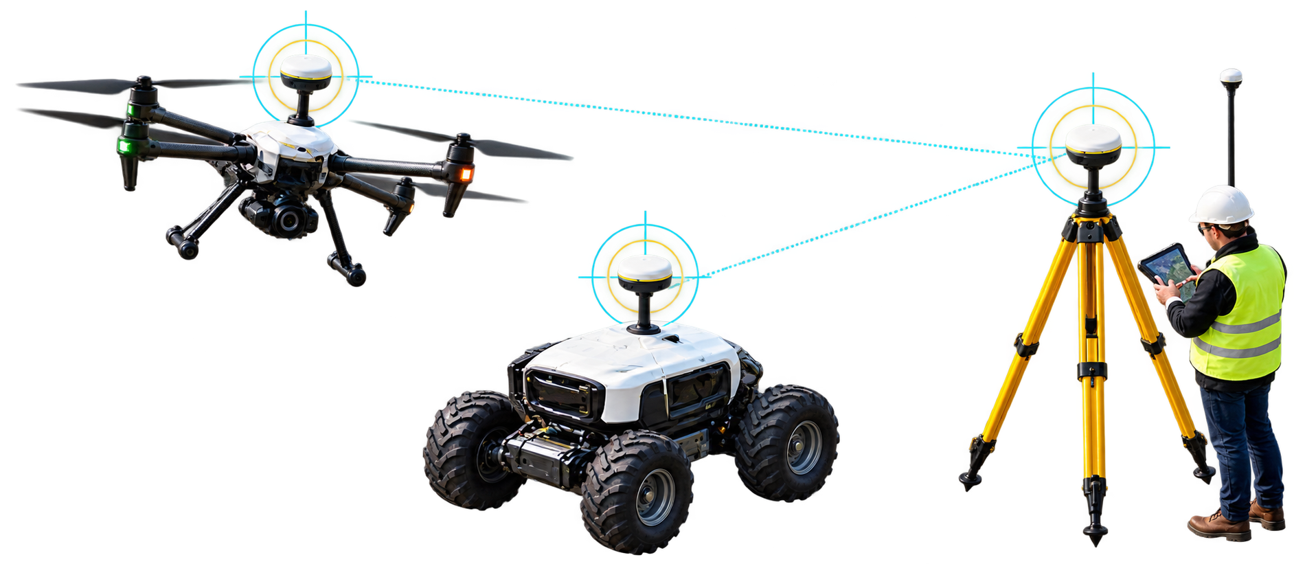
RTK stands for real time kinematic. Real time means the receiver computes its corrected position continuously, not after the data has been collected and processed. Kinematic means the receiver is allowed to move; the term separates the technique from static surveying, where a receiver stays on one point for minutes or hours. The technique is written as real time kinematic, real-time kinematic, and real time kinematics. All three refer to the same method.
ESA’s Navipedia notes that RTK has origins dating back to the mid-1990s. It became common in surveying first, and agriculture, construction, mapping, robotics, and drones followed as receivers became smaller and less expensive.
Why standard GPS is accurate to meters, not centimeters
GPS.gov states that GPS-enabled smartphones are typically accurate to within a 4.9 m (16 ft) radius under open sky, and that accuracy worsens near buildings, bridges, and trees. The U.S. government also commits to a daily global average user range error of 2.0 m or less, with 95 percent probability, for the signal in space. That figure applies to the broadcast signal and does not describe the accuracy a receiver achieves, which depends on satellite geometry, signal blockage, atmospheric conditions, and receiver design and quality.
Much of the error comes from sources shared by receivers in the same neighborhood. A reference receiver at a known location can measure those shared errors directly and pass them to a rover. That principle is the basis of differential GNSS, and RTK extends it from code measurements to carrier-phase measurements.
Error sources and how RTK treats them
| Error source |
Cause |
Treatment in RTK |
| Ionospheric delay |
Charged particles in the upper atmosphere slow the signal. |
Largely cancels between a rover and a nearby base. Dual-frequency receivers can also estimate it. |
| Tropospheric delay |
Pressure and water vapor in the lower atmosphere delay the signal. |
Cancels at short distances. It is the first error to decorrelate as the baseline grows. |
| Satellite clock error |
Onboard clock offset from system time. |
Cancels in differencing. |
| Satellite orbit error |
Broadcast orbit differs from the true satellite position. |
Cancels over short baselines. |
| Receiver clock offset |
Local oscillator offset. |
Cancels in double differencing. |
| Multipath |
Signals reflect from buildings, ground, and vehicle bodies before reaching the antenna. |
Not corrected. Reduced by antenna choice, antenna placement, and multi-band tracking. |
| Receiver noise and interference |
Thermal noise, RF interference, and jamming. |
Not corrected. Reduced by receiver design and interference mitigation. |
How RTK works
Carrier phase measurements
A standard receiver estimates the distance to each satellite from the code carried on the signal. Navipedia gives the typical error of code pseudorange measurements as around 1 m, compared with about 5 mm for carrier-phase measurements. The difference comes from wavelength. The GPS L1 carrier has a wavelength of about 19 cm, and a receiver that tracks the phase of that wave to within 1 percent resolves distance to about 2 mm.
The integer ambiguity problem
Carrier phase has one limitation. A receiver can measure where it sits within a single wave cycle but cannot tell how many whole cycles lie between the satellite and the antenna. That unknown whole number is the integer ambiguity. A one-cycle error on L1 produces an error of about 19 cm, which is far outside the target for centimeter work.
RTK removes most of the other unknowns through double differencing. The rover forms differences between its measurements and the base station’s measurements, and between two satellites. Receiver clock offsets, satellite clock offsets, and hardware biases cancel, and the remaining ambiguity is an integer. Navipedia describes the resolution in three steps:
- Estimate the ambiguities as real numbers with least-squares techniques. The result is the float solution.
- Search for the set of integers that best fits the float solution and leaves the smallest residuals.
- Apply the integers to the carrier measurements and compute the rover position relative to the base station.
The second step is the difficult one. The float estimate has a long, narrow region of uncertainty, so a brute-force search is too slow for receiver hardware, and receivers use search methods built for that shape. When one set of integers is clearly better than all others, the receiver reports a fixed solution.
The RTK process from base to rover
- A base station sits on a surveyed point and tracks the same satellites as the rover.
- The base sends its observations and its position to the rover as RTCM messages over a data link.
- The rover forms double differences between its own measurements and the base measurements.
- The rover resolves the integer ambiguities.
- The rover computes its position relative to the base and adds the base coordinates, which places the result in the global coordinate frame.
Relative accuracy and absolute accuracy
RTK positions are relative to the base station. Two rovers served by the same base agree with each other to within centimeters, but their absolute position carries any error in the base coordinates. If the base position is off by one meter, every rover position shifts by one meter. Establishing the base coordinates correctly, through a long observation or a connection to a reference network, is part of any RTK installation.
RTK solution states: single, differential, float, and fixed
A receiver reports how much confidence it has in each position. In NMEA 0183 output, the GGA sentence carries a fix quality value that applications read to decide whether the position is usable.
| Solution state |
What it means |
Typical accuracy |
GGA quality value |
| Single |
No corrections applied. Code measurements only. |
Several meters |
1 |
| Differential (DGPS or SBAS) |
Code-based corrections applied. |
About 1 m |
2 |
| RTK float |
Corrections received. Integer ambiguities not yet resolved. |
Decimeter level |
5 |
| RTK fixed |
Integer ambiguities resolved. |
1 to 2 cm |
4 |
Fixed is the state to use for any action that depends on centimeter accuracy. A rover that has received corrections but has not fixed its ambiguities is in float and can be off by a decimeter or more. Confirm the quality values against the documentation for your receiver.
What determines RTK accuracy
Baseline distance
RTK assumes that the atmosphere above the base and the rover is almost the same. As the distance between them grows, the two atmospheres diverge and ambiguity resolution becomes less reliable. Navipedia gives a service area of about 10 to 20 km for a single base station and notes that the troposphere is the first error to decorrelate, within a few kilometers. Network RTK and virtual reference station methods extend coverage by modeling the atmosphere across a region.
Receiver specifications express this as a fixed term plus a distance term in parts per million (ppm), where 1 ppm equals 1 mm of error per kilometer of baseline. The Ezurio GW16160 specification lists RTK accuracy of 0.6 cm + 0.5 ppm horizontal and 1 cm + 1 ppm vertical. Applying that formula gives the following expected errors.
| Baseline distance |
Horizontal error |
Vertical error |
| 1 km |
0.6 cm + 0.05 cm = 0.65 cm |
1 cm + 0.1 cm = 1.1 cm |
| 10 km |
0.6 cm + 0.5 cm = 1.1 cm |
1 cm + 1 cm = 2.0 cm |
| 20 km |
0.6 cm + 1.0 cm = 1.6 cm |
1 cm + 2 cm = 3.0 cm |
These values come from the manufacturer’s specification and apply under the conditions stated in the datasheet. Field results vary with sky view, multipath, and correction quality.
Sky view and multipath
RTK requires continuous tracking of carrier phase. Navipedia notes that RTK needs continuity in the tracked measurements and calls this a severe limitation in urban environments, where many obstructions interrupt the signals. After a break, the receiver typically has to resolve the ambiguities again. Practical steps that protect the fix:
- Mount the antenna with open sky in every direction and away from tall structures.
- Keep metal surfaces, vehicle bodies, and cable runs away from the antenna to reduce multipath.
- Use an antenna with a stable phase center and a proper ground plane.
- Separate the antenna from motors, power lines, switching supplies, and radio transmitters.
Satellite count and geometry
More constellations put more satellites in view and improve geometry. Better geometry shortens the time to a fixed solution and helps the receiver hold the fix when part of the sky is blocked. See the Ezurio FAQ on the four global GNSS constellations for the system list.
Correction quality and latency
Corrections that arrive late or with gaps reduce fix reliability. Receivers typically limit how old a correction can be before they stop using it, so the design of the data link matters as much as the choice of receiver.
Atmospheric disturbance
Ionospheric activity during solar events increases errors and can slow or prevent a fix. GPS.gov lists major solar storms among the less common causes of degraded GPS accuracy.
Multi-band and multi-constellation receivers
RTK-capable receivers track more than one frequency from each satellite. The GPS signals differ in wavelength.
| GPS signal |
Frequency |
Wavelength |
| L1 |
1575.42 MHz |
About 19.0 cm |
| L2 |
1227.60 MHz |
About 24.4 cm |
| L5 |
1176.45 MHz |
About 25.5 cm |
Two frequencies help in two ways. First, ionospheric delay depends on frequency, so two measurements let the receiver estimate and remove it. GPS.gov states that using two GPS frequencies improves accuracy by correcting signal distortions caused by Earth’s atmosphere. Second, differencing the L1 and L2 phase measurements produces a combined signal with a wavelength of about 86 cm. The receiver resolves that long wave easily and then uses the result to narrow the search for the 19 cm cycles. This is why a multi-band receiver reaches a fixed solution faster than a single-band receiver. The Ezurio FAQ on single-band and multi-band GNSS covers the basics.
The antenna must cover every band the receiver tracks. An L1-only antenna on a multi-band receiver removes the benefit of the second frequency.
Multi-constellation tracking adds satellites. GPS (United States), GLONASS (Russia), Galileo (European Union), and BeiDou (China) are the four global systems. QZSS (Japan) and NavIC (India) are regional systems. Ezurio explains the difference between the two terms in its FAQ on GNSS and GPS.
Where RTK corrections come from
RTCM and NTRIP
RTCM is the correction message format defined by the Radio Technical Commission for Maritime Services. NTRIP, the Networked Transport of RTCM via Internet Protocol, is the protocol that streams those messages over the internet from a server called a caster to a client. A receiver that supports RTCM input accepts the stream as bytes on a serial or USB port and applies it internally, so the host software rarely needs to decode the messages.
| RTCM message |
Content |
Purpose |
| 1005 / 1006 |
Base station antenna reference point. Message 1006 adds antenna height. |
Tells the rover where the base is. |
| 1074 / 1077 |
GPS observations in MSM4 or MSM7 format. |
Carrier-phase and code data for GPS. |
| 1084 / 1087 |
GLONASS observations in MSM4 or MSM7 format. |
Carrier-phase and code data for GLONASS. |
| 1094 / 1097 |
Galileo observations in MSM4 or MSM7 format. |
Carrier-phase and code data for Galileo. |
| 1124 / 1127 |
BeiDou observations in MSM4 or MSM7 format. |
Carrier-phase and code data for BeiDou. |
| 1230 |
GLONASS code-phase biases. |
Lets the rover combine GLONASS signals from different receiver types. |
MSM stands for Multiple Signal Message, and MSM7 carries the highest resolution. The messages a base sends must match the messages the rover accepts, so confirm the supported set in the receiver datasheet. Data rates run from hundreds of bytes per second to a few kilobytes per second depending on constellations and message types, which is low enough for cellular, radio, and LoRa links.
Correction sources compared
| Source |
How it works |
Range or coverage |
Typical data link |
Best fit |
| Own base station |
A reference receiver on a surveyed point sends RTCM to rovers. |
Tens of kilometers |
UHF radio, cellular, internet |
Fixed-site operations with in-house GNSS expertise |
| Public reference stream |
Government or institutional reference stations publish RTCM over NTRIP. |
Varies by station |
Internet |
Occasional field work and development |
| Network RTK or VRS |
A network models errors across a region and synthesizes a virtual reference near the rover. |
Network footprint |
Internet (NTRIP) |
Fleets and multi-site operations |
| PPP-RTK or SSR service |
Orbit, clock, and atmosphere parameters are broadcast and applied by the rover. |
Regional to continental |
Internet or satellite (L-band) |
Wide-area deployments that need scale |
| SBAS |
Free regional augmentation from geostationary satellites. |
Regional |
Satellite broadcast |
Meter-level improvement, not centimeter level |
Observation-space and state-space corrections
Observation-space representation (OSR) delivers corrections as composite observations for a rover’s location. Single-base RTK, network RTK, and virtual reference stations use it, and any RTK receiver can apply it. State-space representation (SSR) delivers each error source separately, including orbits, clocks, and atmospheric delay, and the rover rebuilds its own correction. One broadcast stream serves every user, which scales to large fleets, but the receiver needs firmware that supports the format. The Ezurio GW16143 lists SPARTN, SSR, and SBAS support alongside RTCM 3.x.
Data links for corrections
- Internet over cellular, Wi-Fi, or Ethernet, using NTRIP, for network and public streams. Ezurio offers cellular solutions for the link.
- UHF or other radio for a local base station, which works without internet coverage.
- LoRa for long-range, low-rate links, since RTCM streams need little bandwidth. See Ezurio LoRaWAN modules.
- Satellite delivery, such as L-band, for areas without cellular coverage. The GW16143 product page also names the Gateworks GW16130 Iridium Satellite Modem and GW16132 CAT-M1 modem as options for the augmentation data link.
RTK compared with other positioning methods
| Method |
Corrections used |
Typical accuracy |
Time to full accuracy |
Infrastructure |
| Standard GNSS |
None |
Several meters |
Immediate |
None |
| SBAS |
Geostationary broadcast |
Meter level |
Immediate |
Satellite broadcast |
| DGPS |
Code-based, from a local reference |
About 1 m |
Immediate |
Reference station and link |
| RTK |
Carrier phase, real time |
1 to 2 cm (fixed) |
Seconds to minutes |
Base station or network, plus link |
| PPK |
Carrier phase, applied after collection |
Centimeter level |
After post-processing |
Base station data or network logs |
| PPP |
Precise orbit and clock products |
Decimeter to centimeter level |
Tens of minutes |
Correction service |
| PPP-RTK |
Orbit, clock, and atmosphere models |
A few centimeters |
Seconds to minutes |
Regional correction service |
Accuracy and convergence for correction services depend on the provider, so treat the table as typical ranges and check each service specification. RTK and PPK both use carrier phase for centimeter results. RTK applies corrections while the receiver operates, which suits machine control and navigation. PPK records raw observations and corrects them afterward, which suits drone mapping when position does not drive a live control loop.
What an RTK system needs
- An RTK-capable receiver that tracks carrier phase on two or more frequencies and supports RTCM input.
- A multi-band antenna with open sky view and a ground plane.
- A correction source, either your own base station or a network or satellite service.
- A data link that delivers corrections continuously with low latency.
- A host processor and software that read position output, forward corrections to the receiver, and monitor fix status.
Adding RTK to an embedded design
Survey instruments package the receiver, antenna, radio, and battery in one housing. An embedded product separates them. The receiver is a module, the correction link belongs to the host system, and the application consumes the position output.
Socketed card or chip-down module
A chip-down module gives the smallest footprint, but your team owns the RF layout, power design, and certification risk. A socketed card installs in a standard slot, so the product gains precision GNSS without a GNSS receiver design on its own board. The Ezurio FAQs on GNSS modules and form factors cover both options.
Ezurio RTK GNSS cards
Ezurio offers RTK GNSS cards in the Gateworks GW product family. The cards install in M.2 and Mini-PCIe slots on Gateworks single board computers and on other carrier boards with a compatible slot. The table compares the GW16143 and the GW16160 using their product pages.
| Specification |
GW16143 |
GW16160 |
| Form factor |
Mini-PCIe |
M.2 A/E-Key 3042 |
| Constellations |
Concurrent GPS, GLONASS, Galileo, and BeiDou reception |
GPS, GLONASS, BeiDou, Galileo, QZSS, NavIC, SBAS, and L-band; 448 hardware channels |
| RTK operation |
RTK, SSR, and SBAS correction support; base and rover operation |
5-constellation RTK; base and rover |
| Stated accuracy |
Centimeter level, under 2 cm (conditions in Note 1 on the product page) |
RTK: 0.6 cm + 0.5 ppm horizontal; 1 cm + 1 ppm vertical |
| Update rate |
High update rate for mobile applications; rate not stated on the product page |
Up to 100 Hz |
| Host interface |
USB signaling on the Mini-PCIe connector |
USB 2.0 signaling on the M.2 connector; optional Ethernet with onboard PHY |
| Other interfaces and features |
Two UART headers for correction data; PPS time pulse output header; rechargeable 3.3 V lithium battery for faster acquisition |
MicroSD slot for data logging; AIM+ anti-jamming and anti-spoofing interference monitoring |
| Antenna connector |
MMCX; optional u.FL |
Low-profile right-angle MMCX with 3.3 VDC antenna bias |
| Typical operating current |
0.1 A |
0.1 A |
| Operating temperature |
-40 °C to +85 °C |
-40 °C to +85 °C |
| Dimensions |
30.0 x 60.8 x 11.5 mm |
31.0 x 42.8 x 4.2 mm |
The GW16143 product page lists NMEA, UBX, SPARTN, RTCM 3.x, SSR, and SBAS as supported protocols and recommends an external active multi-band antenna, sold separately. The GW16160 product page lists the GW16151 M.2 adapter as an accessory for Mini-PCIe slots. Complete specifications and datasheets are on each product page, and the GNSS modules page shows the full lineup.
Integration steps
- Choose the antenna. It must cover every band the receiver tracks, sit on a ground plane, and have open sky. The GW16143 antenna connects through MMCX, and the GW16160 uses a low-profile right-angle MMCX connector with 3.3 VDC antenna bias. Ezurio also offers antenna design and integration services.
- Install the card. Seat it in the M.2 or Mini-PCIe slot and attach the antenna.
- Connect the host. The GW16160 communicates over USB 2.0, and the GW16143 uses USB signaling on its Mini-PCIe connector.
- Read the output. The GW16143 lists NMEA and UBX among its supported protocols. Position messages carry latitude, longitude, altitude, and fix quality.
- Obtain corrections. Run an NTRIP client on the host to receive RTCM from a caster over cellular, Wi-Fi, or Ethernet, or receive it from a local base station.
- Forward the corrections. Send the RTCM bytes to the receiver’s input port. The GW16143 provides two UART headers for correction data via serial.
- Monitor fix status. Gate any centimeter-dependent decision on a fixed solution, using the GGA quality value or the receiver’s own status messages.
- Plan for dropouts. Define what the system does when the fix is lost, such as continuing on float output, switching to an inertial sensor, or stopping.
Each card’s product page lists a Gateworks software wiki and Linux support under software and development tools.
Where RTK is used
- Surveying and mapping. Field crews verify points in real time and recollect doubtful points in the same visit.
- Precision agriculture. Guidance systems steer tractors along planned paths and reduce overlap and gaps.
- Construction and mining. Machine control compares equipment position with the design surface as work proceeds.
- Drones. Aerial mapping and inspection use RTK or PPK for georeferenced imagery.
- Autonomous robots and vehicles. Outdoor platforms follow paths and hold lanes using centimeter-level position. See Ezurio’s robotics solutions.
- Asset tracking and field data collection. Equipment and assets are located precisely in yards, ports, and worksites.
The Ezurio product pages list autonomous systems, robotics, surveying, agriculture, mining, industrial automation, drones, and outdoor asset tracking among the target applications for the GW16143 and GW16160.
Limitations of RTK
- Corrections are required. A fixed solution depends on a base station or correction service and on a link that delivers it.
- Distance limits accuracy. Error grows with baseline length, and a single base station covers tens of kilometers at most.
- Open sky is required. RTK does not work indoors, and dense canopy or urban canyons can prevent or interrupt a fix.
- Initialization takes time. The receiver needs seconds to minutes to resolve ambiguities after power-on or signal loss.
- Absolute accuracy depends on the base. Errors in the base coordinates carry into every rover position.
- Interference affects tracking. GPS.gov lists radio interference and jamming among the causes of degraded accuracy. Receivers with interference monitoring and mitigation reduce the exposure.
- Heading needs more than one antenna. A single antenna reports direction of travel only while the platform moves. Heading at standstill requires a dual-antenna receiver or GNSS combined with an inertial sensor.
These limits explain why production systems often pair RTK with inertial sensors. Position from RTK corrects drift in the inertial sensor, and the inertial sensor carries the position through short outages.
Frequently asked questions
What is the difference between GPS and RTK?
GPS is a satellite constellation operated by the United States. RTK is a technique applied to GPS and other constellation signals to improve accuracy. A standard GPS receiver reaches several meters, and an RTK receiver with corrections from a nearby base station or network reaches 1 to 2 centimeters when it has a fixed solution.
What does RTK GPS mean?
RTK GPS means real time kinematic GPS: carrier-phase positioning with real-time corrections. The term persists from when GPS was the only constellation. Current RTK receivers use GPS, GLONASS, Galileo, and BeiDou, so RTK GNSS describes them more precisely.
How does RTK GPS work?
A base station at a known location observes the satellites and sends its observations to a rover. The rover compares them with its own carrier-phase measurements, resolves the whole-cycle ambiguities, and computes its position relative to the base at centimeter accuracy.
What is the difference between GNSS and RTK?
GNSS is the category of satellite navigation systems, including GPS, GLONASS, Galileo, and BeiDou. RTK is a positioning technique applied to GNSS signals. A GNSS receiver without RTK support produces meter-level positions. The Ezurio FAQ on how RTK reaches centimeter-level accuracy gives a short version.
What is the difference between RTCM and RTK?
RTK is the positioning technique. RTCM is the format of the correction messages the technique uses, defined by the Radio Technical Commission for Maritime Services. NTRIP is one protocol for streaming RTCM messages over the internet.
Is RTK better than GPS?
For centimeter accuracy, yes, but it requires corrections, a multi-band receiver, and open sky. For navigation and general location, standard GPS meets the need at lower cost and complexity. The right choice depends on the worst-case position error the system can tolerate.
How much does an RTK GPS system cost?
Cost has four parts: the RTK receiver module or card, a multi-band antenna, a correction source, and the integration effort for the data link and software. Some public correction streams are free, and network services charge a subscription. For pricing and availability of the GW16143 and GW16160, contact Ezurio.
What are the disadvantages of RTK?
RTK needs a correction source and data link, loses accuracy with distance from the base, requires open sky and continuous satellite tracking, and takes time to fix after a signal loss. It does not work indoors.
Can RTK work without my own base station?
Yes. A network RTK or PPP-RTK service supplies corrections over the internet or by satellite, so you do not install a base station. A reference receiver still generates the corrections, and the service operates it. Accuracy and convergence depend on the service and the distance to its nearest stations.
How far can an RTK rover be from the base station?
For a single base station, Navipedia gives a service area of about 10 to 20 km. Network RTK and virtual reference stations extend usable coverage by modeling the atmosphere across a region. Accuracy still degrades with distance, as the ppm term in receiver specifications shows.
Does RTK work indoors or under heavy tree cover?
RTK needs line of sight to the satellites and continuous tracking, so it does not work indoors. Dense canopy blocks and reflects signals and can prevent a fixed solution. Systems that must keep working through such areas combine RTK with inertial sensors or other localization methods.
Next steps
RTK GPS reaches centimeter accuracy by measuring carrier phase, resolving integer ambiguities, and applying real-time corrections from a base station or network. The result depends on three factors the designer controls: a multi-band receiver that tracks several constellations, a correction source and link matched to the operating area, and an antenna with a clear view of the sky.
Ezurio’s GW16143 and GW16160 cards add RTK to embedded designs through standard Mini-PCIe and M.2 slots. Compare the cards on the GNSS modules page, or talk to an Ezurio GNSS engineer about accuracy, interface, and antenna requirements for your application. Gateworks joined Ezurio through the acquisition announced in the Ezurio newsroom.
Sources and further reading