/filters:background_color(white)/2024-10/C625_4_OSMM_SOM_REV00-front.377.png)
/filters:background_color(white)/2026-02/Carbon-AM62L-TI351-front1.497.png)
/filters:background_color(white)/2024-12/CarbonAM67%20front.399.png)
/filters:background_color(white)/2026-06/940-00186-R1-0-front-labeled.png)
/filters:background_color(white)/documentation/4063297636/15/Generic OSM Evaluation Kit.png)
Getting Started
Welcome to the Quick Start Guide (QSG) for Ezurio's OSM Evaluation Kit: ezurio.com/osm. This guide will walk you through the initial setup process and introduce you to the key hardware and software components of the kit. It's designed to help you quickly get up and running, understand what's included, and start exploring the platform. If you encounter any issues or have questions, please visit ezurio.com/support or contact us at support@ezurio.com. As always, let us know about your experience with the EVK — both the good and bad.
The generic OSM evaluation kit is designed for compatibility with our entire line of OSM system on modules. Interposer kits (ending in -IK) are composed of the system on module mounted to an interposer board, and are connected to the evaluation kit board via a pluggable connector. See Unboxing SOM on Adapter Interposer Kits.
The Ezurio OSM evaluation kit (EVK) and SOM interposer kits are designed to prototype your integrated design using an Ezurio OSM module. An OSM module is soldered on the interposer board, which can connect to the OSM EVK by four 120 pin connectors. The Ezurio OSM EVK provides multiple display interfaces, camera, audio, CAN bus, M.2, Gigabit Ethernet and other hardware options for optimal flexibility and user experience.
The EZOMC-000-0000-00000-2-K2 carrier kit comes without a display attached and is stackable via standoffs.
This document describes key hardware aspects of the Ezurio OSM carrier evaluation kit and is applicable to the EVK PCB with revision R5.0.
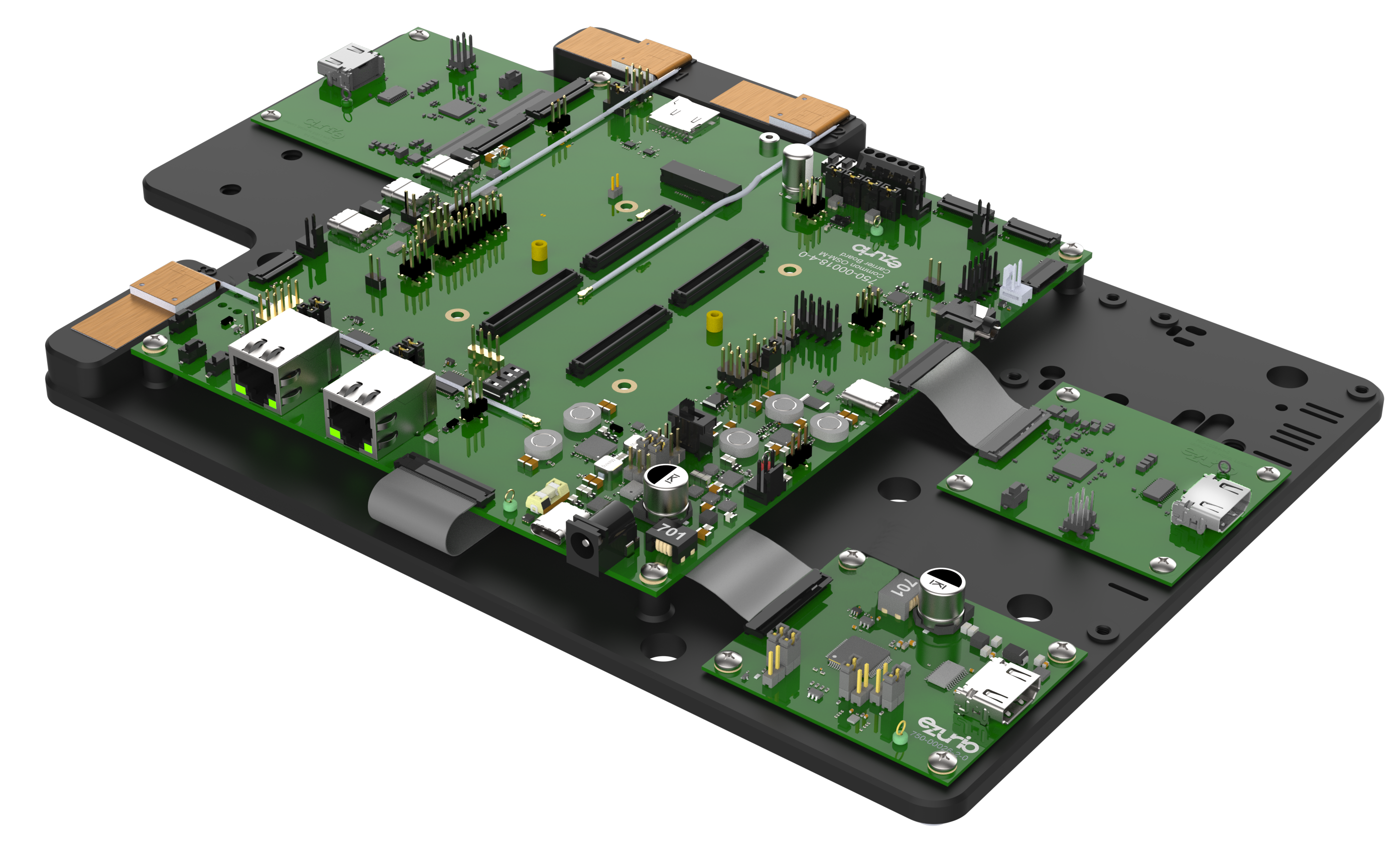
Ezurio Generic OSM Evaluation Kit Part Number
- EZOMI-000-0000-00000-2-K2 (Generic OSM Evaluation Kit: Eval Board / HDMI Adapters / Eval Board / Antennas / Accessories / Interposer board required - sold separately).
Ezurio OSM Boards for Evaluation Kit Part Numbers
Examples below of companion SOM on Adapter (-IK) Interposer kits that can be used with the generic OSM evaluation kit part number above. For complete lists of part numbers, please refer to each product family’s product brief.
- EZOMI-625-0216-00199-2-IK (Carbon AM62 OSM-MF SOM with Adapter: AM62 / 2GB RAM / 16GB eMMC / TI351 Wi-Fi-BT / For Use with OSM EVK).
- EZOMI-625-0216-00134-2-IK (Carbon AM62 OSM-MF SOM with Adapter: AM62 / 2GB RAM / 16GB eMMC / 60 Series Wi-Fi-BT / For Use with OSM EVK).
Unboxing the Generic OSM Evaluation Kit
The following table provides a breakdown of the hardware components included in the Generic OSM Evaluation Kit:
| Item | Additional Description & Details | |
|---|---|---|
| 1 | 1× Assembly, Dev Kit, OSM Carrier | #450-00256 |
| 2 | 1x PCBA, Common OSM-M/OSM-S Carrier Board | #940-00384 |
| 3 | 1x PCBA, Display Adapter Board, RGB to HDMI | #940-00065 |
| 4 | 1x PCBA, Display Adapter Board, 4-Lane LVDS to HDMI, Lontium | #940-00477 |
| 5 | 1x PCBA, Display Adapter Board, MIPI-DSI to HDMI, Lontium | #940-00487 |
| 6 | 1× FLEXPIFA 6e, 2.4-2.5/4.9-7.125GHz, MH4L | #EFB2471A3S-10MH4L with 10 cm cable. |
| 7 | 1x AC Adapter, 12V-3A, EU/US Switch-over Plugs, Barrel Connector, PHY=2.1mm | #223-00014 |
| 8 | 1x Cable, USB-C to USB-C, 1.5 Meter, Black, USB3.2 Gen 1 5Gbps, PD60W, E-Mark. | #133-00034 |
| 9 | 1x Cable, HDMI v2.0, Black, 1.5M, Shielded | #133-00035 |
| 10 | 1x Industrial microSD Card, 32GB, 3D NAND, SDSDQAF4-032G-I | #143-00003 |
Note: All accessories listed above are included unless otherwise stated.
Unboxing SOM on Adapter Interposer Kits
Interposer kits are those whose part numbers end in “-IK”, and include a SOM mounted on interposer.
The following table provides an example breakdown of the hardware components included in the OSM SOM Interposer Kit EZOMI-625-0216-00199-IK: (each kit additionally includes an OSM SOM, and various SOM families are supported)
| Item | Additional Description & Details | |
|---|---|---|
| 1 | 1x PCBA, Interposer Board, Module, CarbonAM62, Quad Core CPU, 2GB LPDDR4, 16GB eMMC, Sona TI351 453-00199 | #940-00584 |
| 2 | 1x Assembly, Heat Sink, CarbonAM6x | #450-00253 |
| 3 | 1x FLEXPIFA 6e, 2.4-2.5/4.9-7.125GHz, MH4L | #EFB2471A3S-10MH4L with 10 cm cable. |
Datasheets, Product Pages & DOCs
The following table provides an overview of available datasheets, product pages, and documentation (DOCs).
| Product | Datasheet | Product Page (+Buy) | Documentation | |
|---|---|---|---|---|
| 1 | Assembly, Dev Kit, OSM Carrier | N/A | N/A | N/A |
| 2 | Common OSM-M/OSM-S Carrier Board | Universal OSM Carrier Support Site | Universal OSM Carrier | Universal OSM Carrier |
| 3 | Display Adapter Board, RGB to HDMI | User Guide – OSM EVK | ||
| 4 | Display Adapter Board, 4-Lane LVDS to HDMI, Lontium | User Guide – OSM EVK | ||
| 5 | Display Adapter Board, MIPI-DSI to HDMI, Lontium` | User Guide – OSM EVK | ||
| 6 | FLEXPIFA 6e, 2.4-2.5/4.9-7.125GHz, MH4L | FlexPIFA 6E – Datasheet | Link | FlexPIFA 6E – Documentation |
| 7 | BD070LIC3 – 7″ Touchscreen Display | See Documentation | Link | Link |
| 8 | Industrial microSD Card, 32GB, 3D NAND, SDSDQAF4-032G-I | Industrial microSD Card | Industrial microSD Card | Industrial microSD Card |
Board Assembly
Always make sure everything is completely powered off and disconnected from any power source before making changes to the board. Doing so while the board — or other parts of it — are still powered can cause irreversible damage to the hardware equipment!
If you purchased the carrier board package and separate OSM module kit, the Carrier Board and OSM interposer board (with OSM module soldered on) arrive disassembled. To assemble, you will need to insert the interposer board into the Carrier Board via the four 120-pin connectors and secure it with the mounting screws.
To assemble, complete the following steps:
- Insert the OSM interposer board into the Carrier Board by aligning it with the four 120-pin connectors (
CON15,CON16,CON17,CON18), ensuring the location pin is oriented correctly for upright installation. - Use the mounting screws to secure the interposer board to the Carrier Board. You can adjust the screen tilt vertically, like a laptop, to match your setup and preferences. If wireless connectivity is required, make sure the antenna is securely connected to the MHF4L connector on the PCB of the radio module.
(Optional) Ezurio recommends the use of the heat sink for high processor utilization use cases and/or high temperature environments. If desired, apply the included thermal interface material to the heat sink, and next install the heat sink to the top of the Carbon AM62 OSM-MF module using the included mounting screws.
See the OSM EVK User Guide for visual references.
Powering On
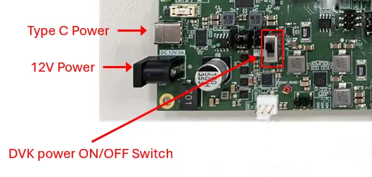
To power on the carrier with the -IK kit installed, plug the 12V AC adapter into the 12V Power barrel connector CON1. Then move the switch labeled “V_SYS” to the “ON” position.
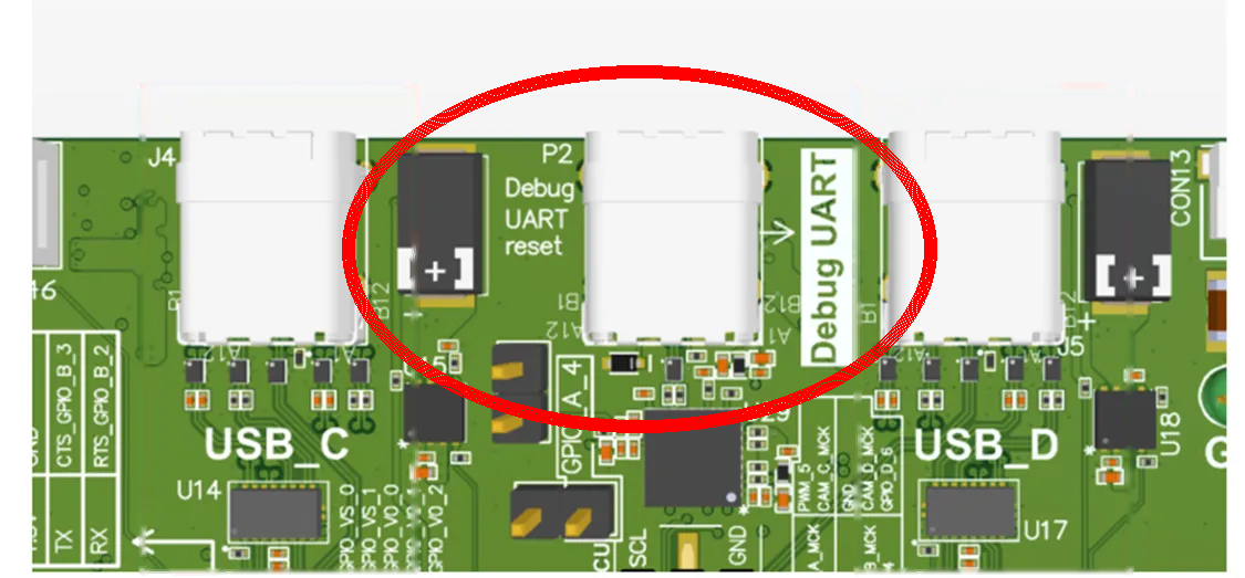
Console debug port
To interact with the the board’s software image once powered on, use a USB-C cable connected to P2, the debug UART port. Most OSM processors support a terminal application at 115200 baud, 8N1.
For first boot experience, please refer to the EVK kit delta guide for your specific OSM SOM processor module family, for example, the AM62 OSM SOM EVK Quick Start Guide.
Display Adapter Boards
For software configuration for your OSM SOM module and operating system, see the EZ BSP Guide.
RGB to HDMI adapter board
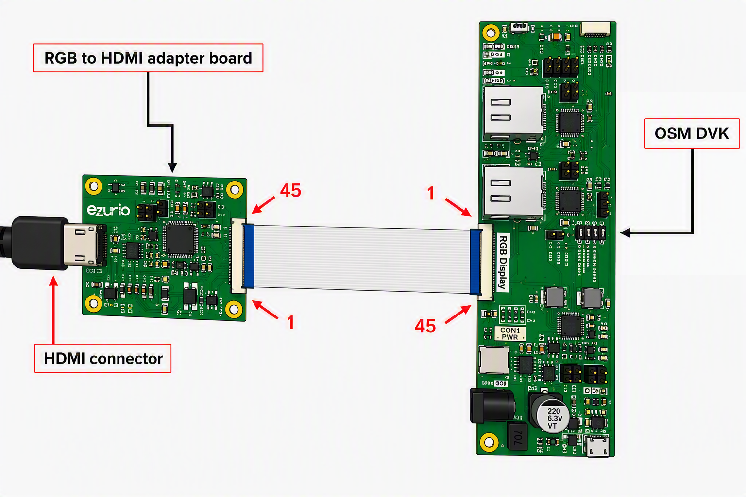
See the OSM EVK User Guide for details of the RGB to HDMI adapter board. The adapter connects to CON7 with a 45 pin dual-side contact connector.
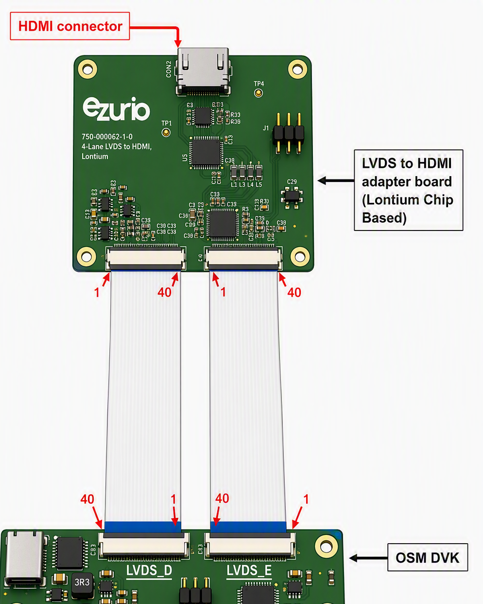
LVDS to HDMI adapter board
See the OSM EVK User Guide for details of the LVDS to HDMI adapter board. 1 or 2 ports configuration can be used. The adapter connects to LVDS_D (CON13) or LVDS_D (CON13) and LVDS_E (CON14) on the OSM carrier board.
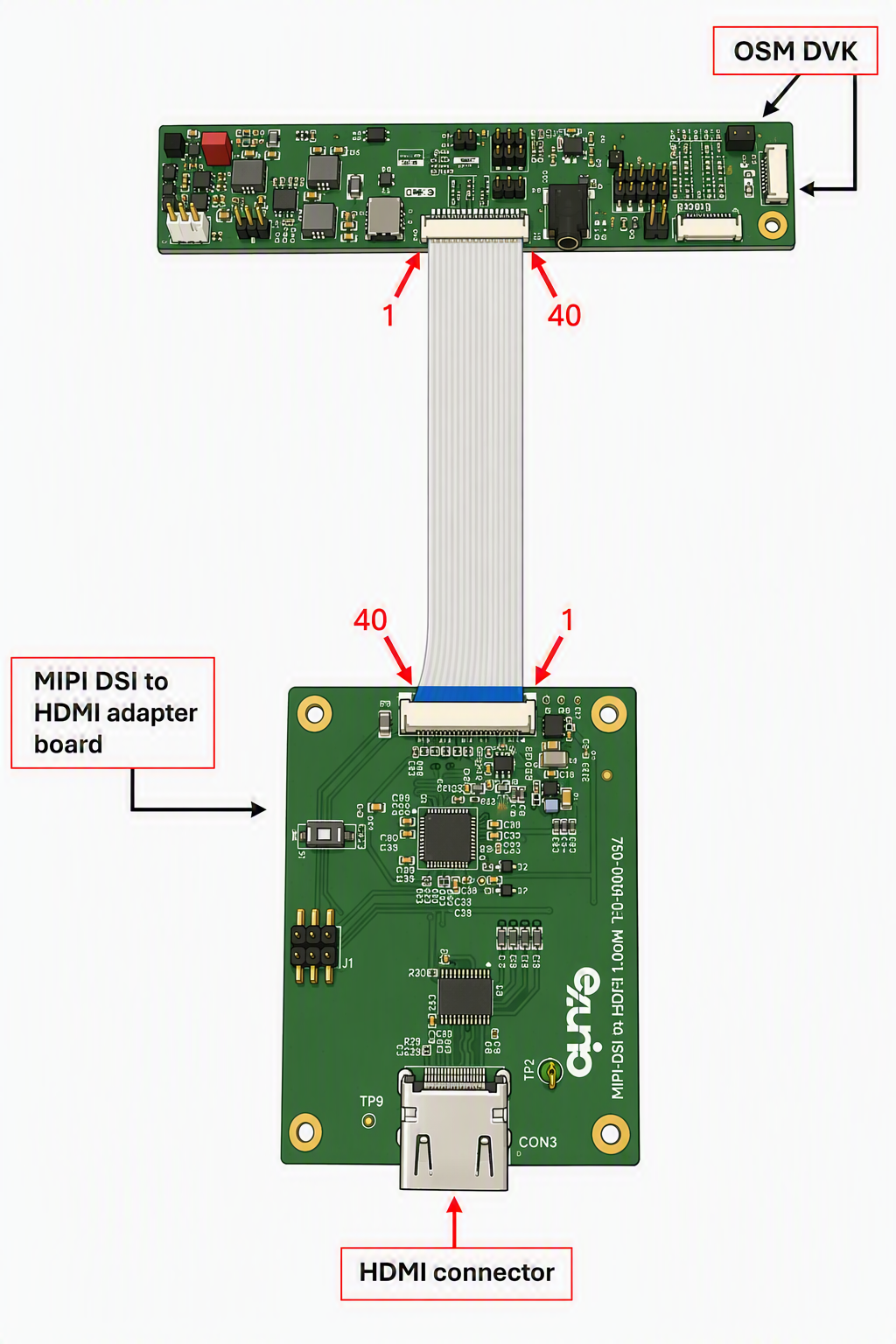
MIPI-DSI to HDMI adapter board
See the OSM EVK User Guide for details of the MIPI-DSI to HDMI adapter board. The adapter connects to CON6 with a 40 pin dual-side contact connector.
Next Steps
Performing a Software Update
See the EZ BSP User Guide.
Building a Custom, EZ BSP-based Image
See the EZ BSP User Guide.
Important Git Repository and Sources
Yocto
- Ezurio Yocto based SOM Release Packages and Manifests →
Summit-SOM-Yocto-Release-Packages: https://github.com/Ezurio/Summit-SOM-Yocto-Release-Packages - Ezurio Yocto meta layer for integrating Ezurio SOMs→
meta-summit-som: https://github.com/Ezurio/meta-summit-som - Ezurio Connectivity Stack Yocto meta layer for integrating Ezurio Wi-Fi radio modules →
meta-summit-radio: https://github.com/Ezurio/meta-summit-radio
Buildroot
- Ezurio Buildroot based SOM Release Packages and Manifests →
Summit-SOM-Buildroot-Release-Packages: https://github.com/Ezurio/Summit-SOM-Buildroot-Release-Packages - Ezurio Buildroot external for integrating Ezurio SOMs->
som-external: https://github.com/Ezurio/som-external - Ezurio Buildroot external for integrating Ezurio Wi-Fi radio modules->
summit-radio-external: https://github.com/Ezurio/summit-radio-external
General
- Ezurio U-Boot →
u-boot-som: https://github.com/Ezurio/u-boot-som
References
- (Ezurio) SOM Documentation → https://www.ezurio.com/support#System-On-Modules-(SOMs)
- (Ezurio) Software Releases → https://www.ezurio.com/resources/software-announcements
- (Buildroot Project) Documentation → https://buildroot.org/docs.html
- (Yocto Project) Documentation → https://docs.yoctoproject.org
- (SGeT Consortium) OSM Standard → https://sget.org/standards/osm