/filters:background_color(white)/2025-07/IF9121.png)
/filters:background_color(white)/2025-07/IF913.png)
Overview
This guide describes how to:
- Build the Wi-Fi Scan example in ModusToolbox™
- Generate the
.heximage - Flash the image to the IF91x DVK
- View Wi-Fi scan results via UART
Note: This guide is current as of April 2026.
Prerequisites
Install the following:
- ModusToolbox™ Tools Package
- Eclipse IDE for ModusToolbox™
(This guide uses Eclipse for ModusToolbox™ 2025.8)
Create the Wi-Fi Scan Project
Launch IDE
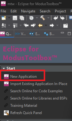
Start Eclipse for ModusToolbox™ 2025.8.
Click New Application.
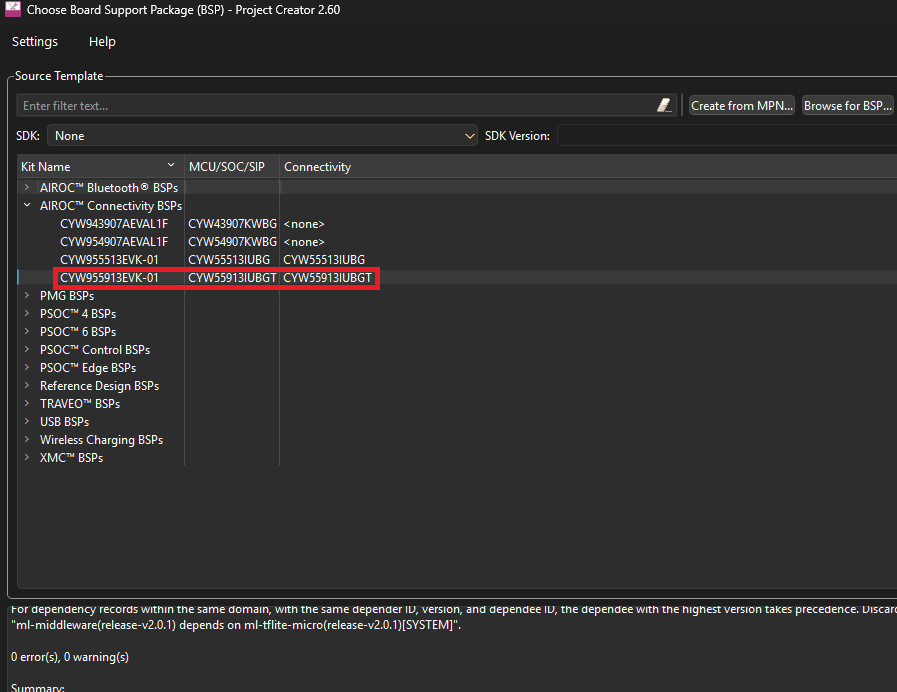
Choose CYW955913EVK-01 as the kit name, then click Next.
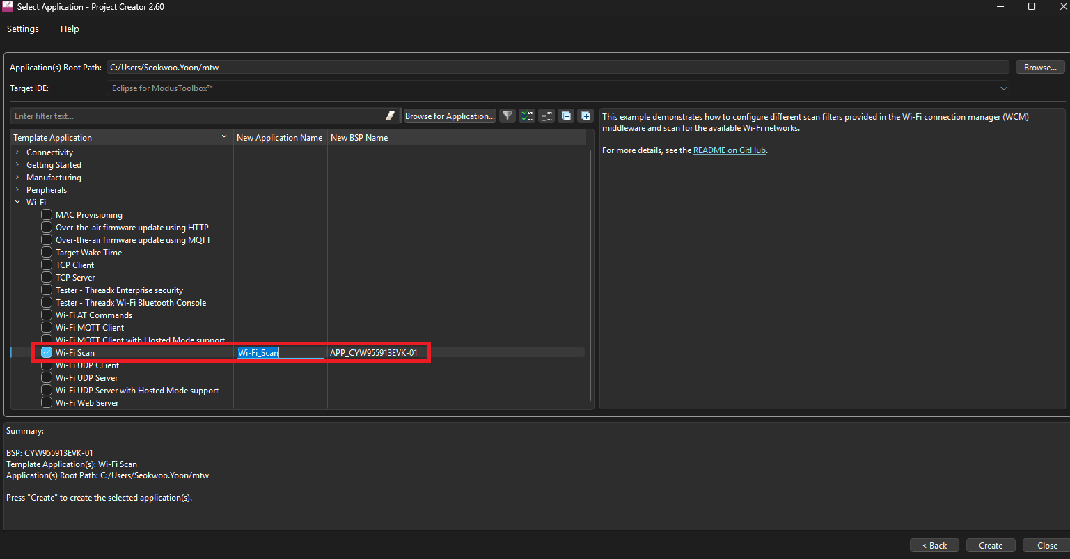
Select Wi-Fi Scan and press Create.
Confirm Project Location
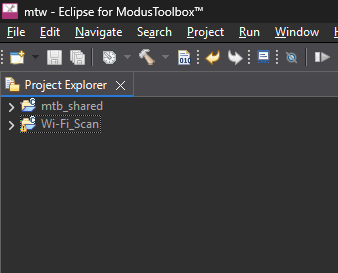
By default, the following folders should be created:
Wi-Fi_Scan
mtb_shared
They are typically located at:
C:\Users\<username>\mtwYou may also navigate using:
%USERPROFILE%\mtwThe project should appear in the left panel under Project Explorer.
If Project Explorer is not visible:
Window → Show View → Project Explorer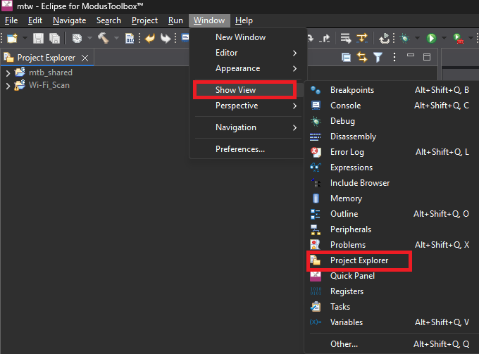
Build the Project
From the menu:
Project → Build All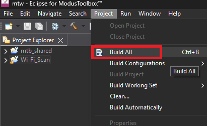 After a successful build, the generated
 .hex file will be located at:C:\Users\<username>\mtw\Wi-Fi_Scan\build\APP_CYW955913EVK-01\Debug\mtb-example-threadx-wifi-scan_download.hexPrepare Flashing Tools
Download and extract [Veda IF91x] Firmware_Script_Log_TestCmd.7z from our website: https://connectivity-staging.s3.amazonaws.com/files/Veda IF91x_Firmware_Script_Log_TestCmd.7z
Copy the generated.hex file into:<Extracted Folder>\FilesIdentify UART Ports
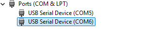
Connect the IF91x DVK via USB.
Open device manager. You will see two COM ports.
To identify them:
- Right-click each COM port → Properties
- Go to Details
Select Hardware Ids
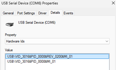
Look for:
| Interface | Identifier | Purpose |
|---|---|---|
| HCI UART | MI_01 | Used for flashing |
| WLAN UART | MI_03 | Used for Wi-Fi scan output |
Example:
- MI_01 → COM6 (HCI UART)
- MI_03 → COM5 (WLAN UART)
Flash the Firmware
The below sequence puts the IF91x DVK into HCI download mode for flashing.
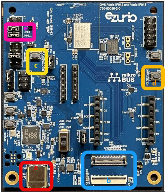
- Press and hold the RECOVERY button (labeled c below)
- While holding RECOVERY, press and hold the RESET button (labeled d below)
- Continue holding both buttons for about 1 second
- Release the RESET
- Wait for 1 second
- Finally, release the RECOVERY
 Open Command Prompt in the extracted
 Files directory.Run:
ifx_flasher_cli.exe -b if91x -c <HCI_COM_PORT> -f mtb-example-threadx-wifi-scan_download.hex -ceExample with the above setup:
ifx_flasher_cli.exe -b if91x -c COM6 -f mtb-example-threadx-wifi-scan_download.hex -ceExpected output:
IFX Flasher CLI v1.0.0
2026-02-11 15:26:48,966 | INFO | Entering HCI download mode on board E664A836A33A412A
2026-02-11 15:26:49,175 | INFO | Loading minidriver...
2026-02-11 15:26:50,906 | INFO | Performing chip erase...
2026-02-11 15:26:53,686 | INFO | Chip erase finished
2026-02-11 15:26:53,686 | INFO | Changing baud to 3000000
2026-02-11 15:26:53,860 | INFO | Programming firmware... (512190 bytes)
2026-02-11 15:27:27,599 | INFO | Finished programming!
View Wi-Fi Scan Results
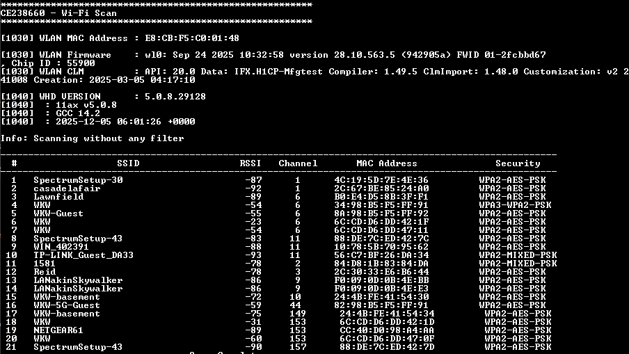
- Open TeraTerm
- Select the WLAN UART COM port (MI_03, COM5 in this example)
- Press RESET on the board
The terminal should display Wi-Fi scan results:
Reference
For more information, see the attached document from Infineon.
https://connectivity-staging.s3.amazonaws.com/files/CYW55913_Software_Develop_Setup_20260123.pdf