/filters:background_color(white)/2024-03/Vela%20IF820%20-%20Modules.png)
Introduction
Overview
This guide contains tutorials for working with the Vela IF820 dual-module Bluetooth® 5.4 Module based on the Infineon Technologies AIROC™ CYW20820 SoC.
Ezurio’s Vela IF820 brings all of Ezurio’s industry competence and capabilities into one solution. The module provides:
- Bluetooth® BR / EDR & Bluetooth® LE v5.4
- Wide range of MCU peripherals: UART, I2C, SPI, ADC, GPIO, PWM, Counter, Timer, Watchdog QSD, Programmable Key Scan
- Industrial Temp Rating (-40° to +85 °C)
- Fully featured development kits
- Powerful Cortex-M4 96MHz Core / 256kB FLASH / 176kB RAM / 1MB ROM
Operating Modes
EZ-Serial
EZ-Serial is a firmware platform built on top of the Vela IF820 Module, providing an easy-to-use method for accessing the most common hardware and communication features for dual-mode Bluetooth® applications. It uses a UART-based API for use with an external host MCU. Ezurio provides open-source Python host samples to test common use cases.
EZ-Serial supports cable replacement capability for both Bluetooth® Classic and Low Energy.
For more information see EZ-Serial Development
HCI
The Vela IF820 includes a HCI UART interface that can be used with an external host. The UART physical interface is a standard, 4-wire interface (RX, TX, RTS, and CTS) with adjustable baud rates from 115200 bps to 3 Mbps.
For more information see HCI Development
Custom Firmware Development
The Vela IF820 is fully supported by the Infineon ModusToolbox™. ModusToolbox™ releases provide the latest ROM patches, drivers, and sample applications allowing customized applications using the CYW20820 to be built quickly and efficiently.
For more information see Custom Firmware Development
Additional Resources
IF820 DVK Setup
The IF820 Development Kit (DVK) is a complete development platform for the Vela IF820 Module. The DVK board provides access to the IF820 Module's interfaces and peripherals, and includes a debug probe for programming and debugging the IF820 Module.
When a Vela IF820 Development Board is plugged into a computer, two COM ports are enumerated. One is the HCI UART, the second one is called the PUART. Programming is done over the HCI UART, and the application uses the PUART to use the EZ-Serial API.
Determining the IDs of IF820 COM Ports
Follow the instructions below to determine which COM Port is the PUART, and which is the HCI UART.
MAC OS using Decisive Tactics Serial Program
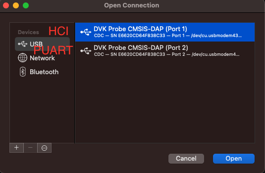
Note: the Port 1 is the HCI Port, Port 2 is the PUART.
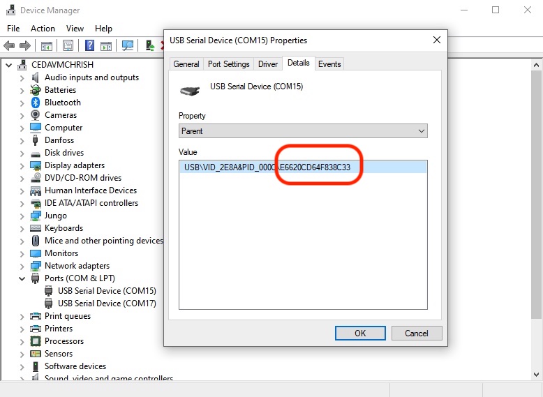
Windows OS using Device Manager
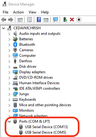
Use Device Manager in Windows to determine the COM Port Number. Right click to view the properties.
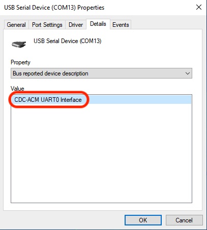
Note: that UART0 is the HCI UART, and UART1 is PUART.
Default UART Parameters
The HCI and PUART interfaces are configured for 115200 baud, 8 data bits, no parity, 1 stop bit.
RTS/CTS hardware flow control is enabled on the HCI UART and should be used by any device communicating with the HCI UART.
DVK Probe
The DVK Probe is an open-source debug solution that is integrated into the Vela IF820 Development Board. The python samples are setup to automatically discover IF820 DVK boards based on this hardware.
Features:
- Dual USB to UART bridge with hardware flow control
- USB to SWD debugger
- USB to GPIO control for richer out-of-the box samples and better automated control of the hardware.
- Single RGB LED for user feedback
Determine DVK Probe Serial Number(s)
Each DVK Probe has a unique serial number. The serial number is used to identify the DVK Probe/IF820 DVK. The DVK Probe Serial Number can be determined from properties of the COM Port.
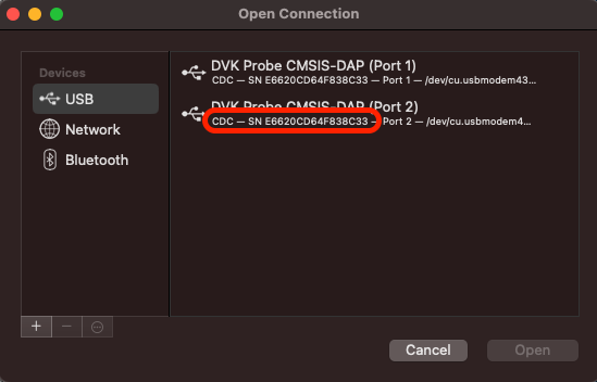
MAC OS using Decisive Tactics Serial Program
Note the DVK Probe ID is circled in red.
Windows OS using Device Manager
Note the DVK Probe ID is circled in red.
Development with EZ-Serial
EZ-Serial is a firmware platform built on top of the Vela IF820 Module, providing an easy-to-use method for accessing the most common hardware and communication features for dual-mode Bluetooth® applications. It uses a UART based API for use with an external host MCU. Ezurio provides open-source Python host samples to demonstrate common use cases.
Setup
-
Ensure you have looked through the DVK Setup to ensure you know how to access the correct COM port.
-
Pull down the Python samples and tests from the Vela IF820 Firmware Repo
-
After pulling the source code, navigate to the firmware directory and run the following command to install the required Python packages:
pip install -r requirements.txt -
Install Visual Studio Code
Visual Studio Code is the IDE used in the example Python host samples. An excellent getting started guide can be found in the Visual Studio Code documentation. It covers everything from setting up Python to debugging and running Python scripts.
Visual Studio Code with Python Tutorial
Getting Started with EZ-Serial
The Vela IF820 Module and Development boards ship with the EZ-Serial firmware already flashed.
A very simple test to setup the UART and test communications is described in the Ping Test.
To check to see if the module is running the latest version of EZ-Serial see the Firmware Update page.
To use the example applications see the Sample Applications page.
To use the Robot Framework tests see the Robot Framework page.
Ezurio BT900 Module
The Vela IF820 module is a new generation replacement for the BT900 module. Some existing Ezurio customers with BT900 solutions will be interested in how the Vela IF820 and BT900 can operate together. The are Python samples that demonstrate common use cases.
More information on the BT900 can be found in the link below. BT900
Additional Resources
[EZ-Serial User Guide - Coming Soon]()
EZ-Serial Ping Test
The Ping Test will connect to a device over the PUART and issue a system_ping command. It verifies communication both ways in the link.
Setup
Connect the IF820 board to a PC via USB.
See Determine COM Port for information on determining the PUART COM Port number and PUART settings.
Ping Test
Once the PUART is opened in the terminal program type /ping in the window.
When the EZ-Serial device receives this command, it will respond with something similar to: @R,001D,/PING,0000,R=000005D0,F=B568.

EZ-Serial Cable Replacement (CYSPP) Quick Start
The EZ-Serial firmware platform for Vela IF820 series module implements a special CYSPP profile that provides a simple method to send and receive serial data over a BLE connection. This operational mode is separate from the normal command mode where the UART API protocol may be used. When CYSPP data mode is active, any data received from an external host will be transmitted to the remote peer, and any data received from the remote peer will be sent out through the hardware serial interface to the external host.
Central Role Setup
To put a device into central mode, pull the CP_ROLE pin low with a wire lead as shown below. 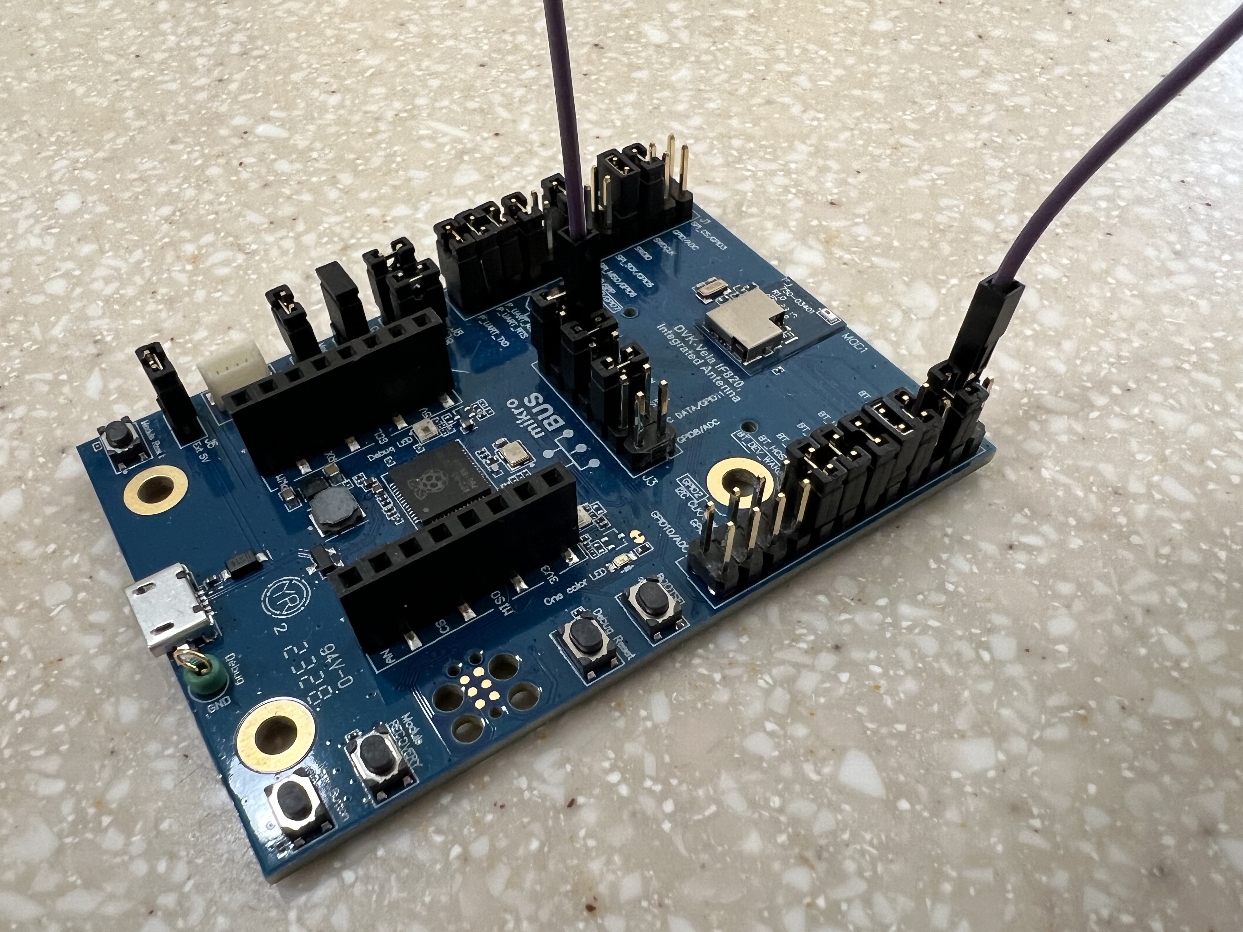
Connect the Vela IF820 board to a terminal program.
Note: The EZ-Serial firmware reads the CP_ROLE pin on startup. It maybe necessary to reset or reboot the board to ensure the pin is read properly.
Peripheral Role Setup
The CP_ROLE pin is pulled up by default, so no special hardware setup is required.
Connect the Vela IF820 board to a terminal program.
Note: The peripheral advertises for 90s and then stops. It maybe necessary to reset or reboot the board if the device stops advertising.
Operation
Once the central and peripheral are booted, they will connect automatically and start CYSPP mode.
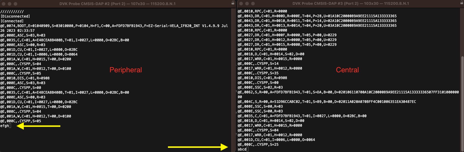
In the image below a terminal session was opened for both devices. The reset button was pressed on each device.
After the devices connected, "abcd" was typed on the peripheral terminal, and it was received by the central terminal.
Then "efgh" was typed on the central terminal, and it was received by the peripheral terminal.
EZ-Serial Firmware Update
The EZ-Serial firmware application is developed and maintained by Infineon. It comes as a compiled hex file. The source code is not available.
Vela IF820 Modules and Dev Kits come with EZ-Serial already installed. Infineon may release an updated version of EZ-Serial and a user may want to update the application.
The programming scripts, in conjunction with the DVK Probe on the IF820 development board, automatically put the device into programming mode.
Obtaining Latest EZ-Serial Firmware
Download EZ-Serial releases here
Note: For EMC compliance reasons, only the releases of firmware above can be used on the Vela IF820.
Determining current EZ-Serial Firmware Version
See Determine EZ-Serial Firmware Version.
Updating Firmware
The firmware can be updated over UART with a Python based programmer CLI or GUI supplied by Ezurio. See Sample Applications for information on how to obtain the source code for the programmer.
It is also possible to update an IF820 running the EZ-Serial firmware over a BLE connection. See OTA Firmware Upgrade.
Specifying Firmware Image
The latest firmware image is supplied with the samples in the files folder.
There is a different firmware image for the internal antenna and the external antenna module variants.
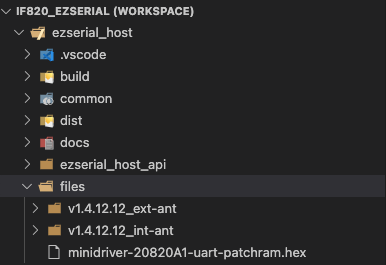
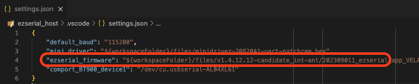
If using the samples in VS code the "ezserial_firmware" attribute in settings.json may need to be updated based on what type of module is being programmed.
Programming
Programming can be invoked using the Flash EZ-Serial [with chip erase] or Flash EZ-Serial [no chip erase] task in VS Code.
See Running Application for information on how to run the sample application and specify parameters.
Alternatively, the if820_flasher_cli.py script can be run directly from the command line to flash firmware.
# Flash internal antenna firmware with chip erase python if820_flasher_cli.py -ce -f files/v1.4.12.12_int-ant/202309011_ezserial_app_VELA-IF820-INT-ANT-EVK_141212_v1.4.12.12_download.hex # Flash external antenna firmware with chip erase python if820_flasher_cli.py -ce -f files/v1.4.12.12_ext-ant/202309011_ezserial_app_VELA-IF820-EXT-ANT-EVK_141212_v1.4.12.12_download.hexYou can remove the -ce option to skip the chip erase. This will preserve the current settings on the device.
You can also add the -d option to enable debug output.
Status
Status can be monitored in the "TERMINAL" window in Visual Studio Code. When programming is complete a Finished programming firmware message will appear in the window.
* Executing task in folder ezserial_host: python /Users/ryan/git/bt20820/ezserial_host/if820_flasher_cli.py -f /Users/ryan/git/bt20820/ezserial_host/files/v1.4.12.12_int-ant/202309011_ezserial_app_VELA-IF820-INT-ANT-EVK_141212_v1.4.12.12_download.hex -ce 2023-10-20 10:14:57,720 | INFO | Programming firmware... 2023-10-20 10:14:59,506 | INFO | Erasing chip... 2023-10-20 10:14:59,506 | INFO | Performing chip erase... 2023-10-20 10:14:59,520 | INFO | Chip erase finished 2023-10-20 10:14:59,520 | INFO | Changing baud to 3mbps... 2023-10-20 10:14:59,524 | INFO | Writing SS section... 2023-10-20 10:14:59,574 | INFO | Writing DS section... 2023-10-20 10:15:08,962 | INFO | Finished programming firmwareOptional: Run Programming in Debug Mode
Select the "Run and Debug" sidebar button. Programming can be done with or without a chip erase. A chip erase will ensure all settings are reset to default values. 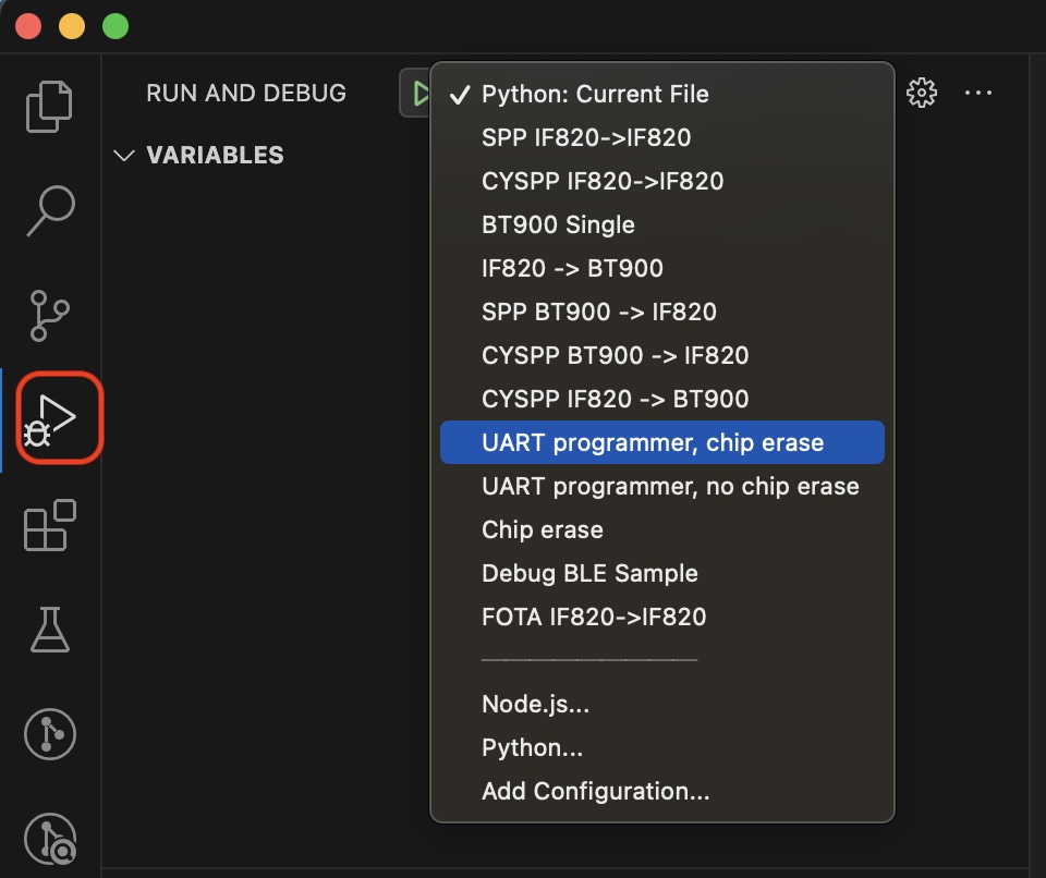
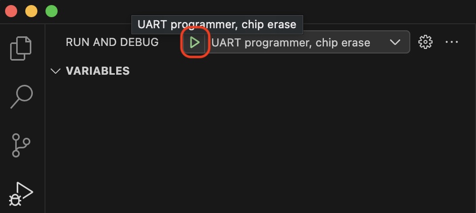
Next click the "Start Debugging" button to start programming.
Putting Device in Programming Mode
The programming scripts, in conjunction with the DVK Probe on the IF820 development board, automatically put the device into programming mode.
The steps to do this manually, if it becomes necessary, are described below.
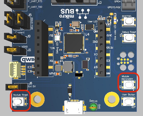
For the device to enter programming mode the "RECOVERY" pin must be asserted when the device boots. The easiest way to do that is to hold down the "Module Reset" and "Module RECOVERY" buttons at the same time. Release the "Module Reset" button so the device boots. After one second release the "Module RECOVERY" button. The device will now be in programming mode.
Determining EZ-Serial Firmware Version
Setup
See here to determine the ID of the PUART COM Port.
Issue Query Firmware API Command
Use the "system_query_firmware_version" /qfv or "system_reboot" /rbt commands to determine the EZ-Serial Firmware Revision. Both commands are illustrated below using a terminal program connected to the PUART.
/qfv @R,002C,/QFV,0000,E=01040C0C,S=03010000,P=0104,H=F1The E field is the EZ-Serial Firmware Revision. In this case it is 01040C0C in hex. This equates to 1.4.12.12
/rbt @R,000A,/RBT,0000 @E,0076,BOOT,E=01040C0C,S=03010000,P=0104,H=F1,C=00,A=FF247F484E50,F=EZ-Serial-VELA_IF820_INT V1.4.12.12 Sep 11 2023 10:17:21The F field is the EZ-Serial Firmware Revision string. This is a more friendly representation of the firmware version.
OTA Firmware Upgrade
if820_ota_tool.py — BLE OTA firmware upgrade tool
A cross-platform command-line tool to perform an over-the-air (OTA) firmware upgrade of EZ-Serial firmware on Infineon / AIROC™ Bluetooth chipsets and modules (e.g. the Ezurio VELA IF820) over BLE.
Find it on Github: https://github.com/Ezurio/vela_if820_ota_upgrade
It is a Python port of the Windows WsOtaUpgrade application and speaks the exact same WICED OTA Firmware Upgrade GATT protocol, using the Bleak BLE library. Because Bleak is cross-platform, this tool runs on macOS, Linux and Windows without the original MFC/WinRT GUI app.
Requirements
- Python 3.8 or newer
- The
bleakpackage (see installation below) - A host with a working Bluetooth LE adapter
- A firmware image built for OTA (e.g.
..._download.ota.bin/*.ota.bin)
python vs python3
The commands below use python3, which is the usual name on macOS and most Linux distributions. On Windows (and some other setups) the interpreter is installed as python instead. Use whichever exists on your system — if python3 is not found, substitute python in every command (and likewise pip for pip3). Once the virtual environment is activated, python and pip inside it always point at the right interpreter regardless of platform.
You can check what you have with python3 --version or python --version.
Installation
From this directory, create a virtual environment and install the dependency:
python3 -m venv venv source venv/bin/activate # Windows: venv\Scripts\activate pip install -r requirements.txtUsage
python3 if820_ota_tool.py <image.bin> [--name "<BLE name>" | --address <BLE MAC>] [--timeout SECONDS]<image.bin>— required. Path to the firmware image to flash.--name— connect to the device advertising this exact BLE name. The name may contain spaces and colons, so quote it.--address— connect directly by Bluetooth MAC address. Not supported on macOS (CoreBluetooth exposes opaque UUIDs, not MAC addresses) — use--namethere.--timeout— BLE scan timeout in seconds (default: 5). Increase it if the device is sometimes slow to be discovered. Applies to both the interactive scan and the--namelookup; it has no effect with--address.
--name and --address are mutually exclusive.
Interactive scan (no target specified)
If you provide neither --name nor --address, the tool scans for ~5 seconds, lists every device whose advertised name starts with EZ-Serial, and lets you pick one by number:
python3 if820_ota_tool.py firmware.ota.binScanning 5 s for devices named 'EZ-Serial...'
Found 2 device(s):
[0] EZ-Serial 85:05:6C D1C2B697-C669-8662-98FC-5A88039577E3 -47 dBm
[1] EZ-Serial 12:34:56 A8F1... -71 dBm
Select device number to upgrade (or 'q' to quit): 0Examples
# Upgrade a specific device by name python3 if820_ota_tool.py firmware.ota.bin --name "EZ-Serial 85:05:6C" # Upgrade by MAC address (Linux / Windows only) python3 if820_ota_tool.py firmware.ota.bin --address AA:BB:CC:DD:EE:FF # Scan and choose interactively python3 if820_ota_tool.py firmware.ota.bin # Give the device longer to show up (15 s scan) python3 if820_ota_tool.py firmware.ota.bin --name "EZ-Serial 85:05:6C" --timeout 15Example run
Loaded firmware image 'firmware.ota.bin' (103228 bytes).
Scanning 5 s for 'EZ-Serial 85:05:6C'...
Connecting...
Connected to D1C2B697-C669-8662-98FC-5A88039577E3.
Detected non-secure OTA firmware upgrade service.
Using data chunk size of 512 bytes.
Transferring: 100% (103228/103228 bytes)
Image CRC32 = 0x1a2b3c4d. Verifying...
Upgrade successful. The device will now reboot into the new firmware.
How it works
The tool implements the WICED OTA Firmware Upgrade protocol over a vendor-specific GATT service. After connecting it:
- Enables notifications on the Control Point characteristic.
- Sends
PREPARE_DOWNLOADand waits for anOKstatus. - Sends
DOWNLOADwith the 4-byte image length and waits forOK. - Streams the image to the Data characteristic in MTU-sized chunks (
MTU − 3, capped at 512 bytes; falls back to 20). - Sends
VERIFYwith a CRC32 of the whole image. OnOKthe device commits the image and reboots into the new firmware.
Both the secure and non-secure OTA services are auto-detected (they share the same Control Point and Data characteristics; only the service UUID differs). The CRC32 is the standard zlib CRC (matching the device's checksum).
Exit codes
| Code | Meaning |
|---|---|
| 0 | Success — firmware upgraded and device rebooting |
| 1 | OTA failed, aborted, or an unexpected error |
| 2 | --address used on macOS (unsupported) |
| 3 | Image file missing, unreadable, or empty |
| 5 | No target device selected / found |
Troubleshooting
-
the 'bleak' package is required— activate the venv andpip install -r requirements.txt. -
Times out waiting for device response — make sure the target is advertising, in range, and not already connected to another host. Move closer and retry.
-
Device stopped advertising - By default the EZ-Serial firmware stops advertising after 90 seconds. Advertising can be restarted by a device reset or with EZ-Serial
gap_start_advcommand. -
--address is not supported on macOS— use--name "<BLE name>"instead. -
Device not found when scanning — the tool matches names starting with
EZ-Serial(case-sensitive). Confirm the device's advertised name. If the device is simply slow to appear, raise the scan window with--timeout(e.g.--timeout 15). -
Verbose debugging — set
IF820_OTA_DEBUG=1to print the Control Point characteristic properties and every raw notification:IF820_OTA_DEBUG=1 python3 if820_ota_tool.py firmware.ota.bin --name "EZ-Serial 85:05:6C"
Warning
Do not power off or disconnect the device during an upgrade. If an EEPROM or serial flash smaller than 64 KB is installed, memory after the upgrade may be corrupted — use the Recover procedure described in the BTSDK application project's README to restore the device.
EZ-Serial Python Samples
Sample applications are provided in Python that demonstrate how to use the EZ-Serial application for common tasks. They can be run as is, or used a the basis for prototyping an end application. Before using any sample applications, the settings file needs to be set up.
The Python samples and tests are available from the Vela IF820 Firmware Repo
The applications are written in Python and designed to be run in Visual Studio Code.
Application Overview
Sample applications are provided for common applications.
Cable Replacement: Examples are provided for cable replacement with both Bluetooth® Classic and Low Energy. These examples show how to communicate with two Vela IF820 devices, or with Vela IF820 and a BT900 device.
Custom BLE behavior: Examples exist that show how to customize the advertisement and GATT table.
Low Power Mode: Examples exist that show how an application can implement low-power modes.
Setting up Visual Studio Code
Connection to PUART of the IF820 and to the DVK Probe are handled automatically by the sample applications. At the start of the script, the needed COM ports and DVK Probes are auto-discovered and setup for use. In the case of the applications where only one board is required, the script will pick the first board in the list. Some scripts require two boards, and the script will ensure that the required number of boards are present.
The exception to this are the sample applications that require a connection to a BT900 device. In this case the COM Port ID will need to be determined and setup in the settings.json file. The COM Port ID from the settings file will in turn be passed to the script via a command line argument from the launch.json or task.json file (depending on if running or debugging). Further reading on how to do this can be found in the links below.
See here for information on setting up the settings file.
See here for information on COM port IDs.
Running Applications
Debugging Applications
Additional Information
See DVK Probe for information on the DVK Probe.
Visual Studio Code Settings
Visual Studio Code Settings File
The settings.json file will need to be created. An example_settings.json file is provided which serves as an example of the contents that need to be in the settings.json file. Make a copy of example_settings.json and rename it to settings.json

See here to determine the ID of the PUART.
See DVK Probe Selection to determine the Serial Number of the DVK Probe.
Specify BT900 COM Port in settings.json
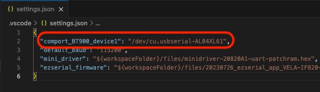
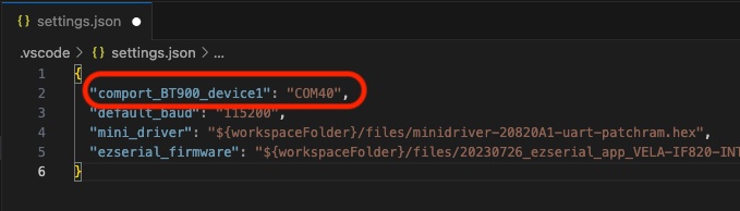
The samples and tests that use a BT900 Device require the UART ID attribute from the settings.json file. Update the settings.json file to use the UART associated with the device.
On Linux or macOS:
On Windows:
Running Samples in VS Code
Open Sample Applications
Using Visual Studio Code, go to File -> Open Workspace from File... and select the if820_ezserial.code-workspace file.
Run Application
In the Terminal Menu select Run Task
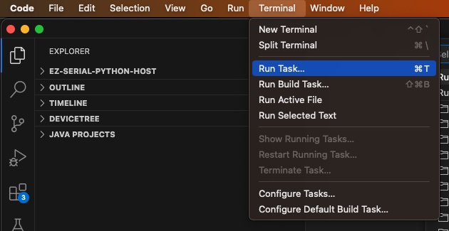
Then select the sample application that you wish to run.
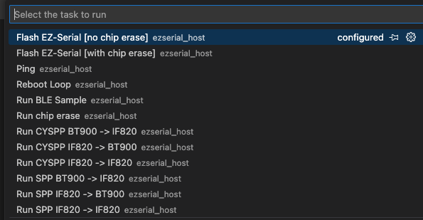
Modify Arguments
Python sample applications typically have a list of arguments that can be passed into the script. Arguments allow different options when running the script.
For example in the if820_flasher_cli.py script, there is an option to perform a full chip erase.
parser.add_argument('-ce', '--chip_erase', action='store_true', help="perform full chip erase.")To modify the arguments passed into the script when running the application, open the tasks.json file and modify the "args" section.
{ "label": "Flash EZ-Serial [with chip erase]", "type": "shell", "command": "python", "args": [ "${workspaceFolder}/if820_flasher_cli.py", "-f", "${config:ezserial_firmware}", "-ce" ], "problemMatcher": [] },Debugging Samples in VS Code
Open Sample Applications
Using Visual Studio Code, go to File -> Open Workspace from File... and select the if820_ezserial.code-workspace file.
Debug an Application
Determine the name of the configuration to launch by opening the launch.json file in Visual Studio Code.
The "program" field contains the name of the python sample.
The "name" field contains the name of the configuration to launch.
{ "name": "CYSPP BT900 -> IF820", "type": "python", "request": "launch", "program": "${workspaceFolder}/sample_cyspp_BT900-IF820.py", "console": "integratedTerminal", "justMyCode": true, "args": [ "-cc", "${config:comport_BT900_device1}", "-d" ] },In the "Run and Debug" window, select the name of the launch configuration determined above. Click the green play arrow button to start debugging the sample. 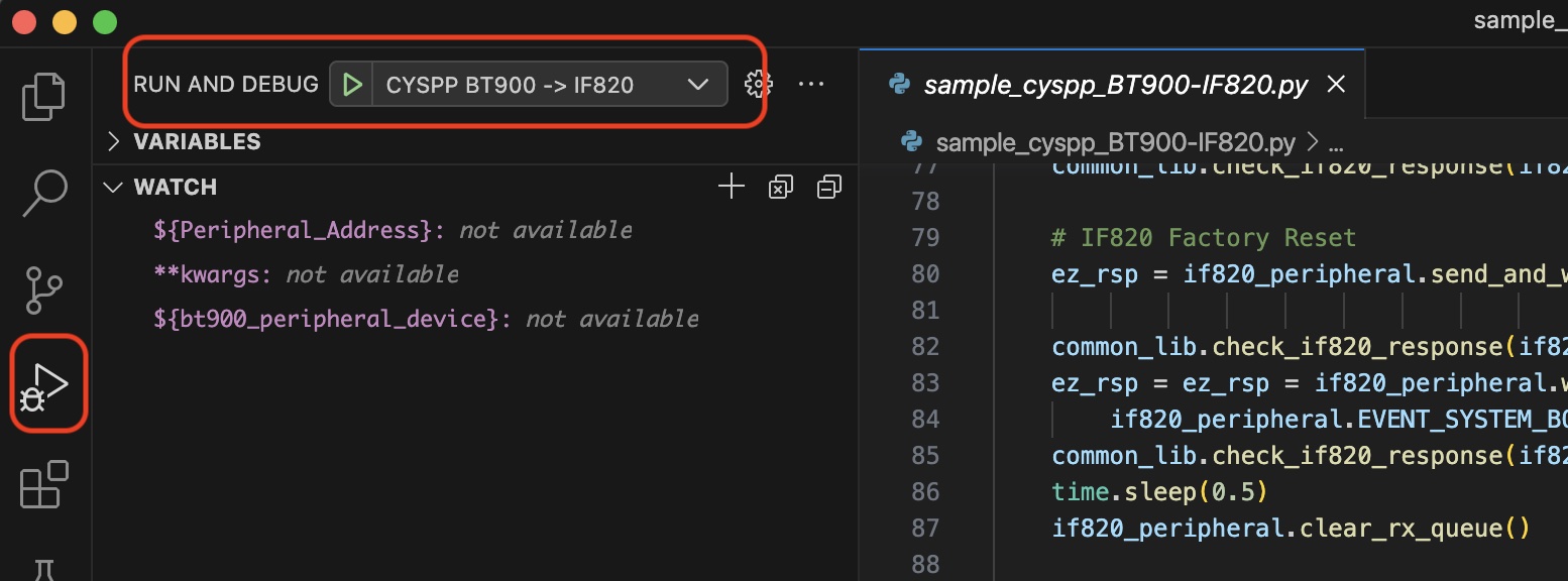
Status
Whether running or debugging a sample application, the status and debug information can be viewed from the TERMINAL window.
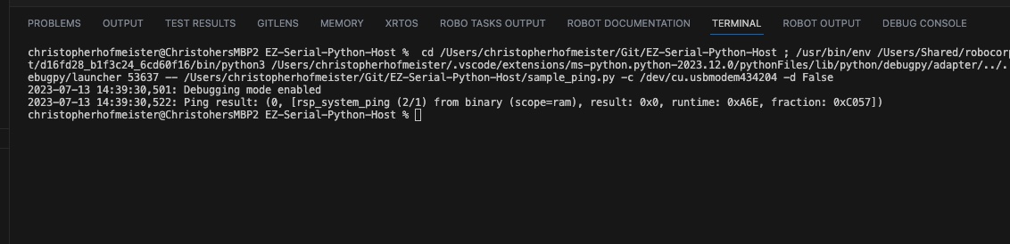
Robot Framework Tests
Along with the Python samples, there are tests written using the Robot Framework.
The Robot Framework tests are used for testing the EZ-Serial firmware APIs. They are not intended for application development.
Users are free to use the tests as is, or use them for a basis of creating new automated tests.
To easily run the tests, install the following extensions in Visual Studio Code:
Using Visual Studio Code, go to File -> Open Workspace from File... and select the if820_ezserial.code-workspace file.
Once opened, VS Code will automatically setup Robot Framework and its dependencies. It can take a few minutes for this to complete.
BT900 Setup
It's only necessary to set up a BT900 board if you're running samples or automated tests that use a BT900 to test the Bluetooth Classic SPP or BLE CYSPP interoperability.
Detailed instructions can be found in the documentation section of the BT900 homepage. The information presented on this page is not designed to replace the existing documentation, but to provide a quick walk-through the the steps that are necessary to setup the BT900.
Update BT900 Firmware
It is a good idea to make sure the BT900 is running the latest firmware. Firmware is available at the BT900 product page.
UwFlashX
UwFlashX is an programming tool developed by Ezurio.
Download and Install from GitHub: UwFlashX
BT900 Firmware
Download the BT900 Firmware
Programming BT900 Firmware
Follow Instructions to program the BT900 firmware.
Install Command Manager Application on BT900 Module
Once the core firmware on the BT900 is updated, a user can program a sample application to run on the module. Command Manager is the Ezurio equivalent of Infineon's EZ-Serial application. Once programmed on the module, the BT900 can communicate with the Vela IF820.
UwTerminalX
UwTerminalX is an enhanced terminal program developed by Ezurio.
Download and Install from GitHub: UwTerminalX
Command Manager Application
Download the Command Manager App from GitHub: Command Manager App
NOTE: You need to download the entire repository. Click the green "Code" button and select "Download ZIP", or pull the code with git.
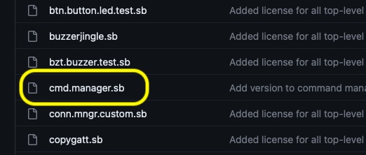
Install Command Manager Application on BT900
Follow the instructions in this Application Note to install the application.
See the section entitled "BT900 Development Kit Setup".
Verify Operation
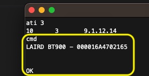
A quick way to check that the firmware is running is to issue a query firmware command "ati 3" as shown in the picture below.

A quick way to check that command manager is working is to issue the command "cmd" as shown in the picture below.
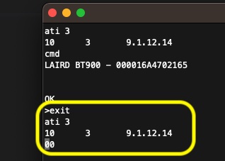
To exit command mode issue the "exit" command as shown in the picture below. Then query the firmware again to verify command manager is not running.
EZ-Serial Low Power Testing
Measurement Setup
A Nordic PPK2 was used to measure the power consumption of the target IF820 DVK.
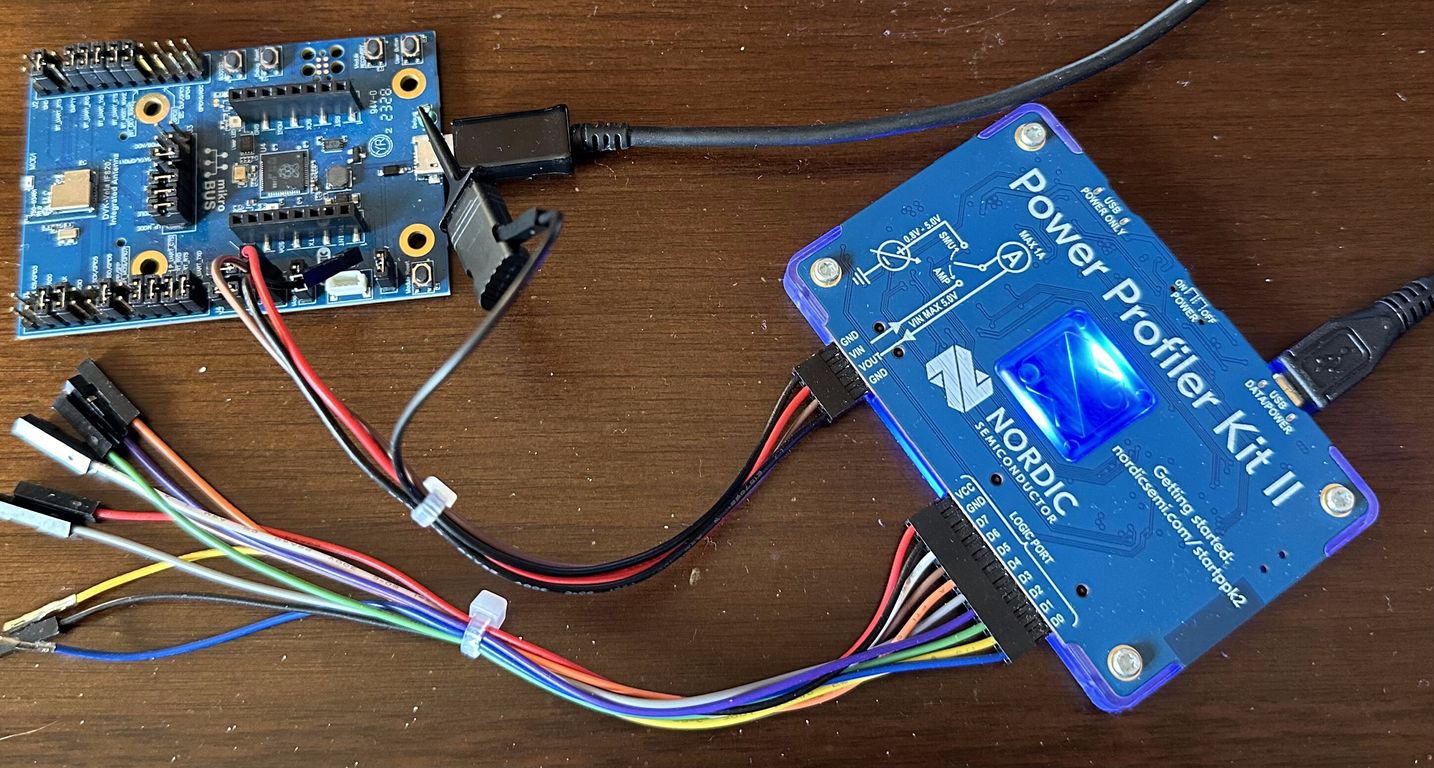
The IF820 devices were tested running v1.4.12.12 EZ-Serial firmware.
BLE Advertising Power Consumption
The advertiser sample was run with the low power option.
Vela_IF820_Firmware: sample: advertiser updated for low power
| Advertising Param | Time (ms) | Notes |
|---|---|---|
| Advertising interval | 250 | |
| Advert data update interval | 2000 | This is the interval at which a host wakes up the IF820, changes the advert data, and then allows the module to go back to sleep. |
The average power consumption is 290 uA over a 60 second measurement period.
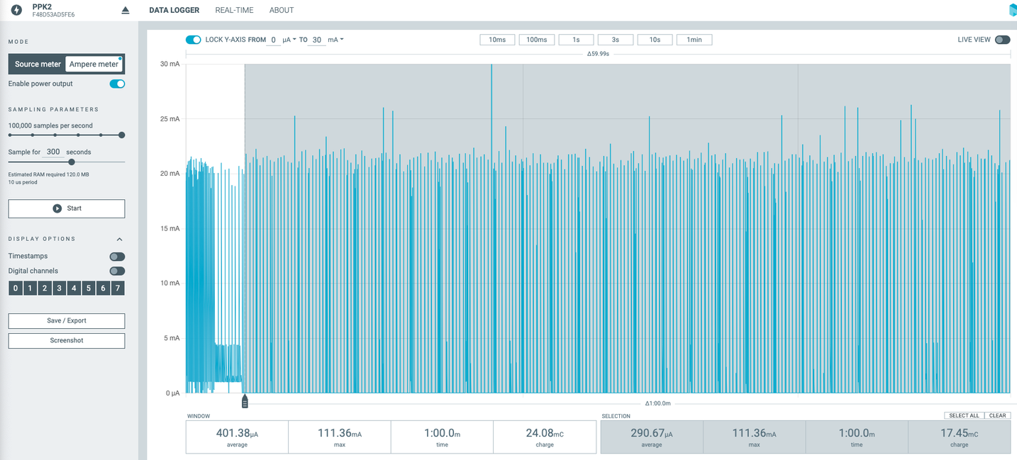
nRF Power Profiler capture data:
advertiser_power_consumption.ppk
BLE Connection Power Consumption
The custom gatt sample was run with the low power option.
Vela_IF820_Firmware: sample: custom GATT updated for low power
| Param | Time (ms) | Notes |
|---|---|---|
| Connection interval | 500 | |
| Supervision timeout | 5000 | |
| Data update interval | 5000 | This is the interval at which a host wakes up the IF820, changes the GATT data, and then allows the module to go back to sleep. |
The average power consumption is 77 uA over 18 seconds in the connection.
PROD-2994: IF820: Connection parameters change after some time
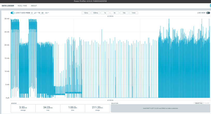
ble_peripheral_connection_power_consumption.ppk
During testing an anomaly was found
After the BLE connection runs for some time, the devices revert to a faster connection interval by themselves. This increases power consumption. A host can monitor for the connection update event to detect this and issue an update connection params command to change the interval back to the desired value.
PROD-2994: Connection parameters change after some time Backlog
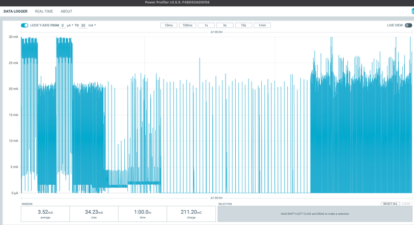
nRF Power Profiler capture data:
ble_peripheral_connection_params_updated.ppk
Bluetooth Classic SPP Power Consumption
The average current consumption for an SPP connection is 2.9 mA.
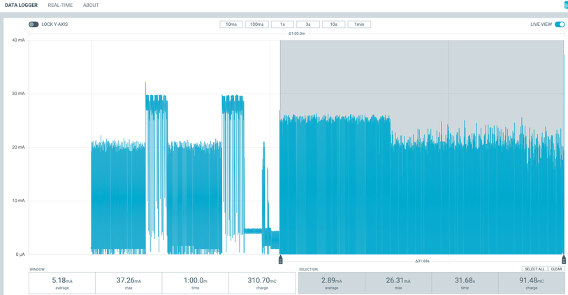
nRF Power Profiler capture data:
bt_classic_spp_power_consumption.ppk
Appendix
EZ-Serial Low Power Modes
| Power Mode | Current Range (typical), Vdd = 3.3 V | Description |
|---|---|---|
| Active | 5 mA to 7 mA | CPU and all peripherals are active. All functionality is possible with no delay. |
| Sleep | 0.23 mA to 3.x mA | In PDS Mode, UART may have missed communication. However, it can still receive data from BLE or BT link. |
| Deep Sleep | 1.2 µA | In HID-Off Mode, no active resources are available until the FW restarts. |
CYW20820 Low Power Modes
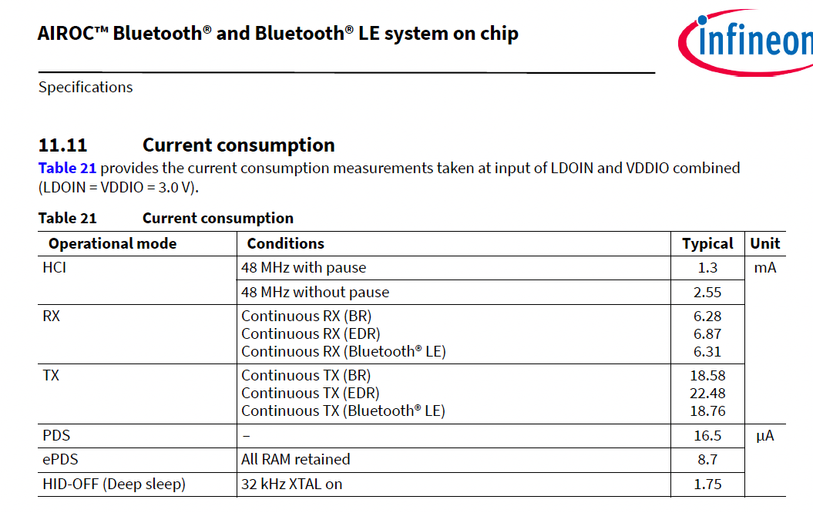
Development with HCI
HCI
It is possible to program the Vela IF820 module with a specific HCI firmware version. The module can then be used as an HCI Bluetooth controller exposing an HCI UART interface.
Obtaining the HCI Firmware
Download the Vela IF820 HCI firmware at the following link:
Programming the HCI Firmware
The HCI firmware can be programmed with the Ezurio programming tools. See here for instructions for programming firmware.
Using the Vela IF820 HCI Module on Linux
Linux usually comes with all necessary tools preinstalled. Those are:
- BlueZ (Official Linux Bluetooth/LE stack)
btattachandbluetoothctl(command line utilities for configuring HCI devices and doing basic tasks)
Connect the Vela IF820 to your Linux PC. The IF820 USB dongle version can be directly plugged into a USB port. When using an IF820 DVK this is simply done by connecting a USB cable.
Open a command shell/terminal on Linux and enter bluetoothctl list. This will return the existing HCI devices. If the PC has an integrated Bluetooth/LE controller, this will be shown as default device.
Attach the IF820 module to the Linux HCI subsystem by setting the proper serial port, baud rate and other parameters.
Note: The btattach command will not return. It will continue to run. Open a new terminal to issue other commands.
sudo btattach -B /dev/ttyACM0 -P h4 -S 3000000Enter bluetoothctl to interact with the bluetooth subsystem. The list command will show the available bluetooth controllers. The IF820 module will now be the default device.
bluetoothctl

[bluetooth]# list
Controller 00:25:CA:B2:06:89 uby #2 [default]
Controller E4:A4:71:47:E6:6C uby
Scan for BLE devices with the scan le command. The devices command will show the discovered devices.
[bluetooth]# scan le
[bluetooth]# SetDiscoveryFilter success
[bluetooth]# hci1 type 6 discovering on
[bluetooth]# Discovery started
[bluetooth]# [CHG] Controller 00:25:CA:B2:06:89 Discovering: yes
[bluetooth]# [NEW] Device 20:6D:31:FB:06:49 Firewalla Gold
[bluetooth]# [NEW] Device 6F:EF:EF:C3:7C:30 6F-EF-EF-C3-7C-30
[bluetooth]# [NEW] Device 1A:0D:AB:3F:96:30 1A-0D-AB-3F-96-30
[bluetooth]# [NEW] Device 73:BA:C5:5A:76:C1 73-BA-C5-5A-76-C1
[bluetooth]# [NEW] Device 55:CA:44:0A:97:3B 55-CA-44-0A-97-3B
[bluetooth]# [NEW] Device 60:25:49:6C:67:25 60-25-49-6C-67-25
[bluetooth]# [NEW] Device 75:C3:D8:54:AB:F3 75-C3-D8-54-AB-F3
[bluetooth]# [NEW] Device 56:58:5F:C0:E1:3F 56-58-5F-C0-E1-3F
[bluetooth]# [NEW] Device 63:33:38:93:2F:45 63-33-38-93-2F-45
[bluetooth]# [NEW] Device 47:8E:99:DC:D3:74 47-8E-99-DC-D3-74
[bluetooth]# [NEW] Device 4A:B6:E8:8C:3E:B6 4A-B6-E8-8C-3E-B6
[bluetooth]# [CHG] Device 6F:EF:EF:C3:7C:30 RSSI: 0xffffffc4 (-60)
Custom Development with ModusToolbox
ModusToolbox SDK
ModusToolbox is a Software Development Kit (SDK) developed by Infineon that can be used to develop custom firmware applications on the Vela IF820.
This document will provide a quick tutorial on how to get started using ModusToolbox. The screenshots shown in this document are based on ModusToolbox for macOS.
Download and Install
Instructions on how to download, install, and use ModusToolbox can be found on the Infineon website.
Hardware Debugging
The Vela IF820 contains a built-in debug probe based on the open source Raspberry Pi picoprobe project. Ezurio has extended the functionality of the probe and has branded it the DVK Probe.
The Vela IF820 development kit user guide is another useful document when developing firmware on the module.
Other information on hardware debugging can be found in the link below.
Creating a new Project
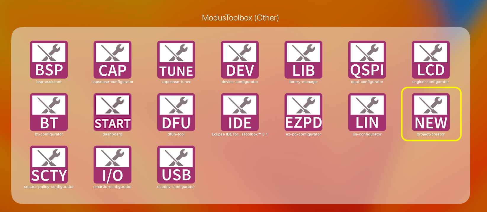
In the "ModusToolbox Other" applications, select "New Project-Creator" as shown in the image below.
Select BSP
In the "Choose Board Support Package" dialog that appears, in the "AIROC Bluetooth BSPs" section, select choose the "CYBT-243053-EVAL" as shown in the image below.
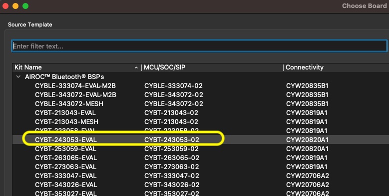
NOTE: Infineon will be adding the Vela IF820 to the list, this image will be updated to reflect this in the future.
Then click the "Next" button in the lower right corner.
Select Project Template
In the "Select Application" dialog that appears two selections must be made.
Target IDE
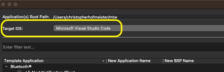
In the "Target IDE" dropdown, select "Microsoft Visual Studio Code".
Template Application
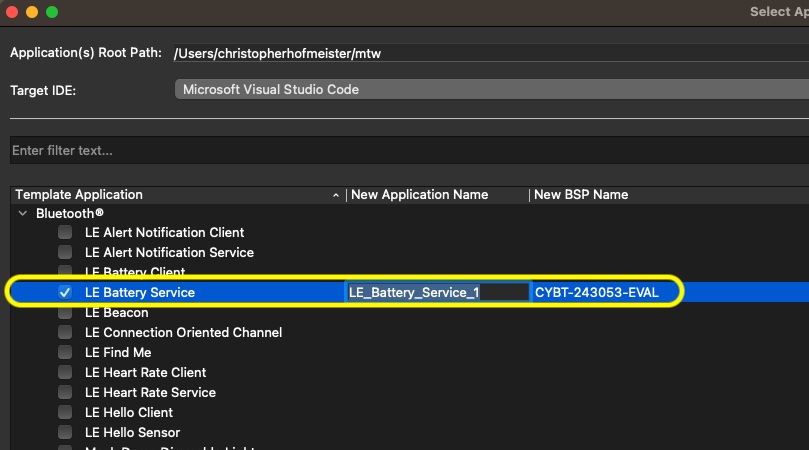
In the "Template Application", select a template that most closely matches the desired application. For example, in the picture below the "LE Battery Service" is selected. Note that the project can also be named in the dialog.
Then click the "Create" button in the lower right corner.
Default Location
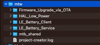
The Application created above will be created in the users home directory, in the "mtw" folder by default.
Running and Debugging an Application
Revision History
v1.2
- Update HCI documentation to use the up-to-date
btattachandbluetoothctlcommands.
v1.1
- Update HCI documentation with new programming instructions.
- Update all Laird Connectivity references to Ezurio.
v1.0
- Initial release
Custom Firmware Development
Debug Firmware with VS Code
Run and Debug Custom Firmware with Visual Studio Code
As shown in Custom Firmware Development ModusToolbox can be used to setup a custom firmware application using Visual Studio Code (VSC). This page will walk a user though the basics of setting up VSC, and running or debugging an application.
Setup
This section will outline the software required to run custom firmware on the IF820 in VSC.
Visual Studio Code Extensions
A few extensions are required, and a number of other extensions, such as code formatting tools can be used.
Cortex-Debug
C/C++ Extension Pack
pyOCD
To install pyOCD, see the Installing section of the documentation on the pyOCD website.
Please note that pyOCD also has it's own software prerequisites (such as Python) which are also outlined in the documentation link above.
Please also note that when running any of the sample applications with EZ-Serial, the pyOCD dependencies are installed automatically since they are part of the requirements.txt file.
pyOCD Configuration
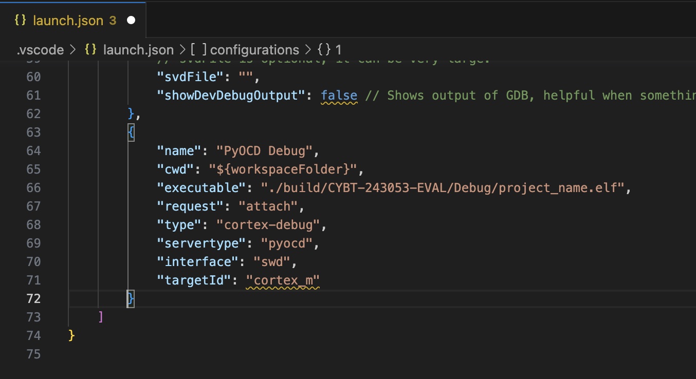
To debug using pyOCD a configuration section needs to be added to the launch.json file in the .vscode folder of the project.
The configuration is shown below so that it can be copied and then pasted into launch.json
{
    "name": "PyOCD Debug",
    "cwd": "${workspaceFolder}",
    "executable": "./build/CYBT-243053-EVAL/Debug/project_name.elf",
    "request": "attach",
    "type": "cortex-debug",
    "servertype": "pyocd",
    "interface": "swd",
    "targetId": "cortex_m"
}
Note: the targetID property cortex_m is the closest match at the time of this writing. Infineon is working on creating a CMIS-Pack for the specific Cortex M that is used on the Vela IF820. In the future that can be used in place of the cortex-m value.
Make File
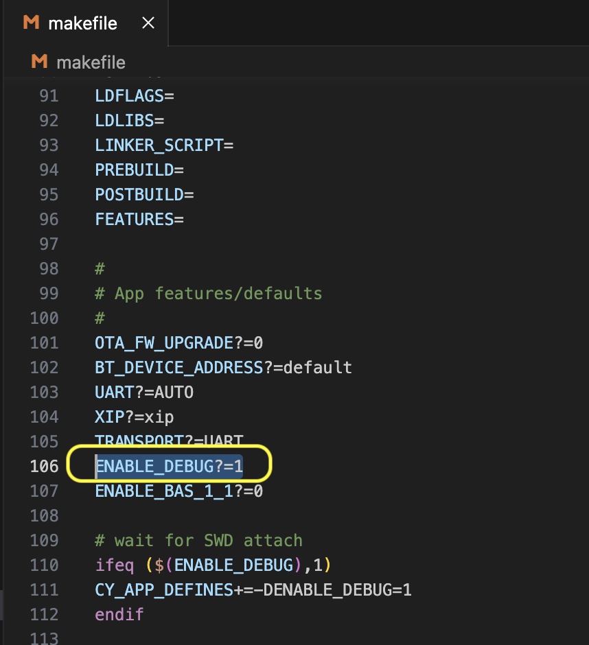
To enable debugging open the makefile and set ENABLE_DEBUG property to 1 as shown in the image below.
Set ARM Toolchain Path
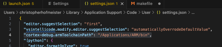
In the user settings (settings.json) the ARM Toolchain should point to the one that ModusToolbox uses.
Building the project
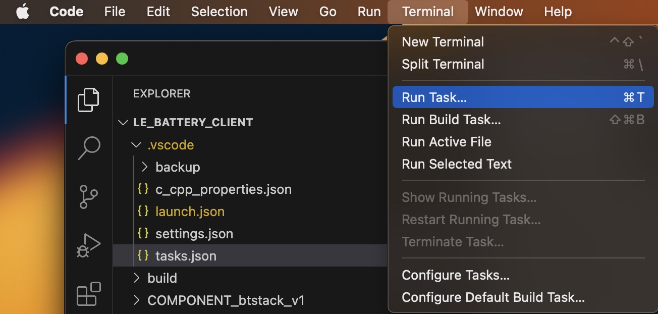
The tasks.json file is setup to run common build actions. Simply click the Terminal-Run menu option
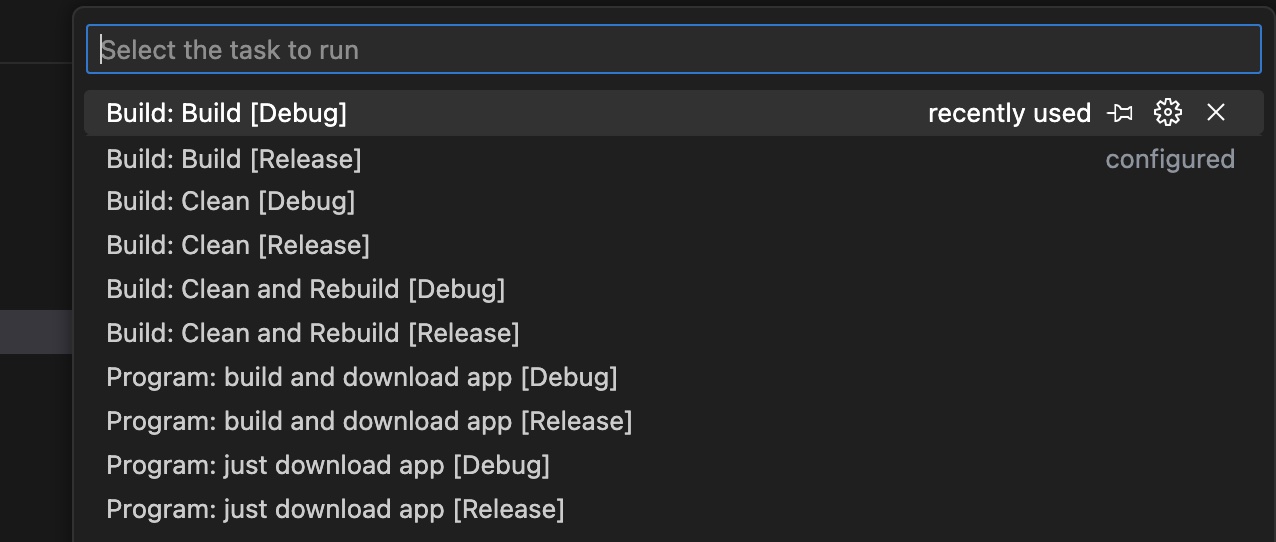
Then select the appropriate task, such as "Build[Debug]"
Selecting a Debugger
To select a debugger, such as the pyOCD debugger described above, navigate to the "Run & Debug" menu and select the debugger from the dropdown menu as shown below.
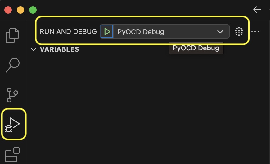
Debugging Project
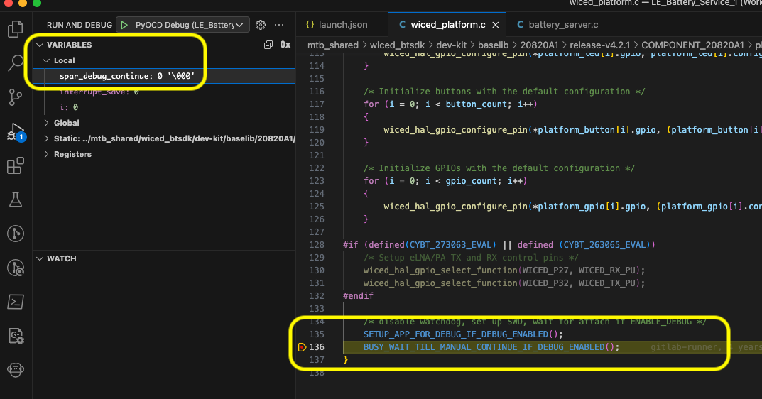
When debugging is started, the project will stop at BUSY_WAIT_TILL_MANUAL_CONTINUE_IF_DEBUG_ENABLED. To continue debugging the user has to set the spar_debug_enable variable to 1 and then continue debugging. This is shown in the image below.